Custom Search
|
|
  |
|
|
Electric Pallet Truck (Low Lift) A typical 6,000-pound capacity electric (low lift) pallet truck is shown in figure 9-54. Several different models of this pallet truck are used at naval activities. Each model of the pallet truck has a two-tine fork that supports a palletized load The tines are raised or lowered by a hydraulic lift mechanism. Depending upon the model, the lift mechanism is either electrically or manually operated The power source for truck traction is a rechargeable battery. It is steered by using the steering handle, with a possible right-angle turn in either direction. The truck is equipped with mechanical brakes, which, when applied, automatically shut off the electrical power. The pallet truck is used to pick up, transport, and deposit palletized loads that do not exceed 6,000
Figure 9-54.-Typical 6,000-pound capacity, low lift, electric pallet truck. pounds. This truck is used on hard and smooth surfaces, such as warehouse and magazine floors. The pallet truck is spark-enclosed when used to handle ammunition. Hand Pallet Truck (Low Lift) A typical 4,000-pound capacity (low lift) hand pallet truck is shown in figure 9-55. Many different models of this pallet truck are used at naval activities. Since the trucks all operate in the same way, the following general description applies to all models. The 4,000-pound hand pallet truck has a two-tine fork that supports a palletized load. The tines are raised or lowered by a hydraulic or mechanical lift mechanism.
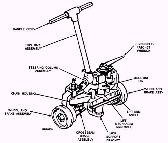
Figure 9-55.-Typical 4,000-pound capacity, low lift, hand pallet truck. The height of lift differs from model to model but is generally in the range of 2 to 4 inches. Depending upon the model, the lift mechanism is operated by the tow handle, a foot pedal, or a hand lever. The truck is not self-propelled and requires manpower for locomotion. It is steered by the tow handle. A right-angle turn is possible in either direction without moving the truck. The drive wheel is located directly beneath the tow handle. It is usually one solid rubber tire. The load wheels, located approximately 6 inches from the ends of the fork tines, can be arranged in a single or double (tandem) fashion under each tine. The hand truck is used to pick up, transport, and deposit palletized unit loads on single- or double-faced pallets that don't exceed 4,000 pounds in weight. This truck is particularly useful and economical for moving loads a short distance. It must be used in areas that have hard and smooth surfaces. MK 45 MOD 2 HANDLIFT TRUCK The Mk 45 Mod 2 handlift truck (fig. 9-56) body is mounted on two wheels equipped with polyurethane tires. The lifting mechanism, which includes a lift arm and a mounting pin for engaging the load, is manually operated by using a reversible, rachet-type, cranking lever to raise or lower the lift arm assembly. A handlebar is connected to the axle for steering the truck. The Mk 45 Mod 2 is intended for use in lifting and maneuvering long, heavy containers and cradles within the weight capacity of two trucks (5,000 pounds). These trucks are used in pairs, with one truck positioned at each end of the container being handled. AERO 33D/E BOMB TRUCK The Aero 33D/E bomb truck (fig. 9-57) is a high-lift bomb truck designed to transport and load stores on
Figure 9-56.-Mk 45 Mod 2 handlift truck.
Figure 9-57.-Aero 33D/E bomb truck with an Aero 62A tray adapter and an Aero 36A outrigger assembly installed. naval aircraft. The major difference between the Aero 33D and the Aero 33E models is that the Aero 33D model has both electric and manual controls, while the Aero 33E model features only manual controls for use with a hydraulic lift system. Except for the electrical features on the Aero 33D, the information contained in the following paragraphs is applicable to both models. The Aero 33 D/E bomb truck is a high-lift, heavy-duty truck. The main frame is welded steel. The hydraulically operated arms have a variable lifting height between 30 and 63 inches. The truck has an SWL of 4,000 pounds. The truck is equipped with front-wheel mechanical brakes that are normally in the locked position. You can release the brakes by actuating the brake release handle on the drawbar or by the deadman brake lever on the drawbar socket. The bomb truck is equipped with an Aero 62A tray adapter (fig. 9-57) attached to the lifting arms. The Aero 62A adapter is a rectangular metal tray, One end is open so the MHU-191 weapon skid can be easily pushed onto the bottom plate. A pair of hooks mounted in two brackets on the bottom of the tray hold the skid in place. The brackets have 40 holes spaced 1 inch apart. This lets you move the hooks to a suitable positions for holding stores of varying lengths. The hooks are secured to the brackets by two detent pins and can be swiveled from a vertical to a horizontal position. A cable assembly provides control of the hooks from outside the tray. You can tilt the tray in the fore and aft vertical plane (20 degrees nose up or 10 degrees nose down) by turning a tilt control crank, located on either side of the truck This lets you horizontally match the store being loaded with the attitude of the aircraft. The bomb truck is a four-wheel vehicle equipped with solid rubber tires. By moving the drawbar, you can rotate the front wheels through an 84-degree arc. When positioning the bomb truck for store loading, you can rotate all four wheels through slightly more than a 180-degree arc as the wheel locking pins are pulled up and disengaged from the wheel swivel. The hydraulic system is suitable for operation at a maximum of 3,000 psi hydraulic pressure. This is required to lift capacity loads with the truck. The hydraulic manual controls are duplicated on either side of the truck. A hydraulic control valve is located inboard and under the left battery box. It actuates part or all of the hydraulic system. With the valve in the open position, you can operate both the left and the right lifting arm simultaneously if either or both of the hydraulic pumps are actuated. Closing the control valve permits manual operation of either the left- or right-hand lifting arm. This is accomplished by manually operating the appropriate left- or right-hand hydraulic pump. When only one lifting arm is being actuated, limit load movements to a few inches. When the control valve is open, both of the lifting arms can be lowered simultaneously by using either the left- or right-hand manual release valves. The manual release valves will lower the lifting arms at a variable rate of speed. Restrict this operation to moving the load only a few inches. The pump speed-control valves have three positions-fast, medium, and slow. The speed-control valve lets the operator adjust the flow of hydraulic fluid from the manual pumps in proportion to the weight of the load-fast for light loads and slow for heavy loads. Set both the left- and right-hand speed controls at the same speed |
 
|
|
|