Custom Search
|
|
  |
|
|
ADU-399/E GUIDED MISSILE HOISTING BEAM The ADU-399/E guided missile hoisting beam (fig. 9-16) is an aluminum weldment that consists of a beam supported on forklift channels and structural members. These components form the base assembly. Rubber-lined cradles mounted fore and aft on the beam prevent metal-to-metal contact. The cradles have side supports held in position by quick-release pins. When you are loading or unloading the beam, remove the quick-release pins to let the side supports swing down out of the way. There are two adjustable tubular extenders on the fore end of the beam that support a vinyl-covered housing. The housing protects the weapon's radome. Quick-release pins secure the extenders to the beam and the radome protector to the extenders. There are cable hoists mounted on the base assembly and held in the hoisting position by quick-release pins. When the pins are removed, the hoists swing down and forward into the stowed position. The ADU-399/E guided missile hoisting beam is used for ground support handling of the Phoenix missile during aircraft loading/unloading operations. This beam may be used in conjunction with the HLU-196B/E bomb hoist, the A/M32K-1A/1B/1C SATS loader, or the ADU400/E weapon skid loading adapter.
Figure 9-16.-ADU-399/E guided missile hoisting beam. MHU-129/E GUIDED MISSILE HOISTING BEAM The MHU-129/E guided missile hoisting beam (fig. 9-17) is an aluminum I-beam with a lifting eye mounted on the top of two removable lifting-shoe assemblies. The shoe assemblies are secured to the lower flange of the beam with quick-release pins designed to engage the forward and aft launch lugs of the Phoenix guided missile. The safety latches in the shoe assemblies secure the beam to the missile. The MHU-129/E guided missile hoisting beam is used aboard ship (aircraft carriers) to handle a previously assembled Phoenix guided missile. MK 37 MOD 0 LIFT BEAM The Mk 37 Mod 0 lift beam (fig. 9-18) is an aluminum alloy beam with an adjustable lifting eye secured to it by two quick-release pins. The suspension lug adapters at each end of the lift beam are used to engage the forward and aft suspension lugs on the Harpoon air-launched missile. A quick-release pin in the aft suspension lug adapter is used for securing the beam to the missile. The Mk 37 Mod 0 lift beam is used with an overhead crane or hoist to lift the Harpoon air-launched missile from the container to the missile assembly stand, or from the missile assembly stand into the container. SLINGS LEARNING OBJECTIVE: Recognize the purpose and use of ammunition handling slings. Slings are lifting devices used to handle weapons. They are made up of various materials, reinforced nylon and heavy cotton mesh, steel cables, welded rings, and safety devices. MK 85 MOD 0, MK 86 MOD 0, MK 87 MOD 0, AND MK 100 MOD 1 PALLET SLINGS The Mk 85, Mk 86, Mk 87, and Mk 100 pallet slings (fig. 9-19) are wire rope basket slings that are adjustable for load height. These slings accommodate a full range of load heights ( 13 to 70 inches) on 40-inch by 48-inch pallets. A section of colored tubing on the cross bridle
Figure 9-17.-MHU-129/E guided missile hoisting beam.
Figure 9-19.-Mk 85, Mk 86, Mk 87, and Mk 100 pallet slings. Table 9-1.-Physical Data for Pallet Slings
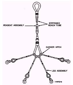
indicates the sling type. Table 9-1 lists physical data for the separate types of slings. MK 105 MOD 0 HOISTING SLING The Mk 105 Mod 0 hoisting sling (fig. 9-20) is a braided nylon rope that consists of a pendent and a leg assembly. Each end of the pendent has a spliced eye, one for the helicopter hook and one for the legs. Legs are rated at 3,000 pounds; with two or more legs, the assembly is rated at 6,000-pound capacity. Longer legs (122 inches) also are available for long or stacked containers. The shorter legs are orange in color; the longer legs are green. MK 109 MOD 0 CONTAINER LIFTING SLING The Mk 109 Mod 0 container lifting sling (fig. 9-21) consists of an adjustable wire rope and chain assembly fitted with a lifting eye and spreader bars. The spreader bars are modified turnbuckles that permit adjustment of sling-leg width within the range of 25 inches to 41 inches. Height adjustment of the bars is provided by the swage stops. The Mk 109 is designed to fit most of the containers and cradles currently in the system.
Figure 9-20.-Mk 105 Mod 0 hoisting sling. H416 BOMB AND CONTAINER SLING The H416 bomb and container sling (fig. 9-22) consists of four wire-rope legs shackled in pairs to each end of a lifting ring spreader bar weldment. Safety hooks are located at each end. |
 
|
|
|