Custom Search
|
|
  |
|
|
F/A-18 GUN SYSTEM INSTALLATION The F/A-18 M61A1 gun system (fig. 6-14) is internally mounted in the nose of the aircraft on the center line. The fired projectiles exit the aircraft through the gun blast diffuser assembly, located just forward of the cockpit windscreen. Depending upon the mission
Figure 6-14.-F/A-18 M61A1 gun installation. 6-15 objective, the gun can be operated in the air-to-ground (A/G) or air-to-air (A/A) computer mode. There are two A/G modes-continuously computed impact point (CCIP) and manual (MAN). There are three A/A modes-director, disturbed, and cage. The pilot can select any one of the A/G or A/A modes while in flight. The ammunition handling system holds a maximum of 578 rounds of ammunition. A rounds limiter, located in the gun compartment, can be preset to limit the total number of rounds the pilot can fire. The rounds limiter is used during training missions, and permits two or three gunnery missions from one gun load-out. For example, the rounds limiter is set at 200 rounds by ground maintenance personnel. When the pilot has fired 200 rounds, the gun's electrical system automatically initiates the gun clearing cycle. This prevents further firing until the rounds limiter is manually reset by ground maintenance personnel. While in flight, the pilot has the option of selecting unrestricted firing or presetting the number of rounds per burst. If the pilot selects unrestricted firing, the gun fires continuously as long as the trigger is depressed and ammunition is available. For example, if the pilot presets 50 rounds, the gun fires a burst of 50 rounds each time the trigger is pulled and released. A display panel in the cockpit continuously indicates the number of rounds remaining. The clearing sector retainer assembly (fig. 6-14) is used to manually clear the gun. When the manual clearing handle is in the cleared position, a wire rope assembly depresses the gun clearing sector assembly against the gun housing. This directs the breech-bolt assemblies into the clearing cam path when the gun is manually rotated. The manual clearing handle is held in the clearing position by a locking tab. For safety reasons, the manual clearing handle should remain in the cleared position until you are actually performing gun-arming procedures. When the gun access door is closed, you can determine the position of the manual clearing handle by the position of the indicator located on the door. If the indicator is flush with the door surface, the manual clearing handle is in the firing position. If the indicator protrudes from the door surface, the manual clearing handle is in the cleared position. The entire gun system is handled as a single palletized unit. This includes the M61A1 gun, drum unit assembly, ammunition chutes, element chutes, and hydraulic motor. The system bolts directly to the aircraft structure with four bolts, and does not require any other boresighting or alignment. Other than minor adjustments in the aircraft, all maintenance is performed at the intermediate-maintenance level. The system is removed from the aircraft as a unit by using gun-handling adapters, a weapon skid or trailer, and an Aero 14C bomb-hoisting unit. The bomb-hoisting unit is used to raise or lower the gun system as it is being removed or installed. A gun system hoist adapter, designed to support the hoist boom, is attached to the aircraft during the raising or lowering operation. A gun-handling adapter, attached to a weapons skid or trailer, supports the gun system after it is removed from the aircraft. For further information concerning the F/A- 18 M61A1 gun installation, you should refer to Description and Principles of Operation, A1-F18AA-750-100; Testing and Troubleshooting, A1-F18AA-750-200; Maintenance, A1-F18AA-750-300; and System Schematics, A1-F18AA-750-500.
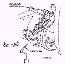
Figure 6-15.-F-14 M61A1 gun installation. F-14 GUN SYSTEM INSTALLATION The F-14 M61A1 gun system (fig. 6-15) is mounted in the forward fuselage on the left side of the aircraft. Depending upon the mission objective, this gun system can be operated in an A/G mode, A/A mode, or an air combat maneuver (ACM) encounter mode. The computer pilot attack mode (ACM encounter mode) operates in conjunction with the weapon control system, computer signal data converter (CSDC), and the vertical display indicator system to display target data. The manual attack mode is normally used in the A/G mode. It is also used as the primary backup for the ACM encounter mode in case of system malfunction. The M61A1 gun system accommodates a maximum of 676 rounds of 20-mm ammunition. There are 576 rounds in the drum and a total of 100 rounds in the chutes, transfer adapter assembly, and gun. The system can be set by ground maintenance personnel for unrestricted firing, or for rounds limit of 50, 100, or 200 rounds per burst. The HOOK/GUN panel contains a gun-rounds counter that gives a digital readout countdown of the rounds remaining in the gun system. The clearing sector holdback assembly and safety pin (fig. 6-16) is used to clear the gun manually. With the clearing sector holdback assembly installed, the breech-bolt assemblies are diverted to the clearing cam path. Keep the clearing sector holdback assembly and safety pin installed until just before aircraft flight.
Figure 6-16.-F-14 clearing sector holdback assembly and safety pin. |
 |
|
|