Custom Search
|
|
  |
|
|
LEARNING OBJECTIVE: ldentify the purpose and recognize the use of guided missile launchers. Identify the components of the LAU-7/A (series) guided missile launcher. Guided missile launchers provide the mechanical and electrical means of suspending and air-launching a guided missile from an aircraft. Because the physical, mechanical, and functional requirements vary for each particular missile-to-aircraft configuration (table 3-2), a brief description of each type of missile launcher is discussed in the following paragraphs. Table 3-2.-Missile Launcher Application
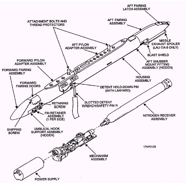
LAU-7/A (SERIES) GUIDED MISSILE LAUNCHER The LAU-7/A (series) guided missile launcher (fig, 3-18) is a reusable launcher that provides a complete launching system for use with the AIM-9 Sidewinder (series) missiles. The launcher (fig. 3-18) has four major assemblies-the housing assembly, nitrogen receiver assembly, mechanism assembly, and power supply. Housing Assembly The housing assembly is the main structural member of the launcher. It is an extruded, machined aluminum member that provides structural rigidity to the launcher and includes provisions for mounting all other assemblies. It also includes provisions for mounting the launcher to the aircraft. Nitrogen Receiver Assembly The nitrogen receiver assembly stores the high-pressure nitrogen (3,200 psig) used to cool the missile's IR detector in the guidance system. Two nitrogen receiver assemblies are available for use with the launcher. One is a cylindrical fiber glass container with a corrosion-resistant metal liner, and the other is a plain cylindrical steel container. The receiver mounts in the aft section of the housing assembly and screws into the aft end of the mechanism assembly. All receivers contain a charging valve (for refilling), relief valve, and a pressure indicator mounted in the aft end of the cylinder. The pressure indicator is color coded to ensure correct readings as follows: Red 0 to 2.2 psi Yellow 2.2 to 2.8 psi Green 2.8 to 3.5 psi White 3.5 to 5 psi All readings listed must be multiplied by 1,000 psi. Mechanism Assembly The mechanism assembly is an electromechanical device that holds the missile for takeoffs and landings and releases the missile for launching. It mounts in the center of the housing assembly forward of the receiver assembly. The subassemblies of the mechanism assembly are discussed in the following paragraphs. ELECTRICAL HARNESS ASSEMBLY.- The electrical harness assembly consists of the appropriate connectors and wiring to interconnect between the aircraft power and firing circuits and the launcher. Also,
Figure 3-18.-LAU-7/A (series) guided missile launcher. the nitrogen system supply tube is routed through the electrical wiring harness to the power supply. DETENT, DETENT LOCK, DETENT-LOCK SOLENOID, AND SNUBBERS.- The detent, detent lock, detent-lock solenoid, and forward snubbers (fig. 3-19) make up an electromechanical system that restricts longitudinal and lateral motion of the mounted missile. This system prevents accidental launch or release during catapult takeoff or arrested landings. A slotted detent wrench/safety pin is installed through the mechanism assembly to prevent movement of the aft detent and to safe the launcher firing circuits. It is also used to raise the aft detent lug sufficiently to clear the missile hanger during loading. The slotted detent wrench/safety pin is removed before flight. When the detent is down (normal), the striker points make contact with the buttons (contacts) on the forward hanger of the missile. The forward striker point does not have a function for the missile; the aft striker point makes contact between the missile and the firing safety switch. |
 |
|
|