Custom Search
|
|
  |
|
|
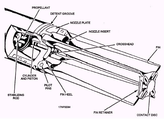
Motors The rocket motor consists of components that propel and stabilize the rocket in flight. Not all rocket motors are identical, but they do have certain common components. These components are the motor tube, propellant, inhibitors, stabilizing rod, igniter, and nozzle and fin assembly. The rocket motors discussed in the following paragraphs are for the 2.75-inch Mk 4 Mods, Mk 40 Mods, the 5.0-inch Mk 16 Mods, and Mk 71 Mods. MOTOR TUBE.- The motor tube (fig. 2-2) supports the other components of the rocket. Presently, all motor tubes are aluminum, threaded internally at the front end for warhead installation, and grooved or threaded internally at the aft end for nozzle and fin assembly installation. The Mk 4 Mods 1 through 6 and the Mk 40 Mod 0 have a nonintegral (two-piece) bulkhead at the forward end of the tube. This bulkhead has a disc that blows out in case of accidental propellant ignition before installation of the warhead. This action neutralizes rocket thrust by allowing gas produced by the burning propellant to escape from both the forward and aft ends of the motor tube, making it nonpropulsive. It is still a fire hazard. All other Mark and Mod motors discussed in this chapter have tubes with integral bulkheads that do not rupture. In case of accidental propellant ignition, these motors are propulsive, becoming a missile hazard as well as a fire hazard. PROPELLANTS.- The propellant grain (fig. 2-2) contained in the Navy's 2.75-inch and the 5.0-inch rocket motors is an internal burning, star perforation, double-base solid propellant. The star perforation is designed to produce a nearly constant thrust level. The Mk 66 rocket motor has the star points machined off (conned) to reduce erosive burning. In addition this propellant grain is 5 inches longer than the Mk 4/40 propellant grain. INHIBITORS.- Inhibitors restrict or control burning on the propellant surface. In the 2.75-inch and the 5.0-inch motors, the propellant grains are inhibited at the forward and aft ends, as well as the entire outer diametral surface. The forward and aft end inhibitors are molded plastic (ethyl cellulose) components bonded
Figure 2-2.-Components of a typical rocket motor. to the propellant ends. The outer surface inhibitor is spirally wrapped ethyl cellulose tape bonded to the propellant surface. Inhibitors cause the propellant grain to burn from the center outward and from forward to aft uniformly. If inhibitors weren't used, the burning surface of the propellant grain would increase, and result in an increased burning rate. This could cause the motor tube to explode from excessive pressure. If a motor is accidentally dropped and the propellant grain is cracked, the crack in the grain increases the burning surface and an identical hazard exists. STABILIZING ROD.- The stabilizing rod (fig. 2-2), located in the perforation of the motor propellant grain, is salt coated to prevent unstable burning of the propellant. It also reduces flash and afterburning in the rocket motor, which could contribute to compressor stall and flameout of the aircraft jet engines. When the propellant ignites, the stabilizing rod ensures that the grain ignites simultaneously forward and aft. IGNITER.- The igniter (fig. 2-2) heats the propellant grain to ignition temperature. The igniter used in the 2.75-inch motor is a disc-shaped metal container that contains a black powder and magnesium charge, a squib, and electrical lead wires. It is located at the forward end of the motor. The igniter used in the 5.0-inch motor is a disc-shaped metal container that contains a powder or pellet charge, two squibs, and electrical lead wires. It is located at the forward end of the motor. A contact disc or a contact band transmits the firing impulses to the motor igniter. The 2.75-inch motor has electrical leads that extend from the squib through the wall of the igniter. They are routed through the propellant perforation to the nozzle fin assembly. One of the wires is connected to the nozzle plate (ground), and the other passes through
Figure 2-3.-Typical center electrical lead wire connection (2.75-inch motor),
Figure 2-4.-Typical center electrical lead wire connection (5.0-inch motor).
Figure 2-5.-Fin protector in place. either one of the nozzles (fig. 2-3, view A) or the fin-actuating piston (fig. 2-3, view B) to the contact disc (fig. 2-3, views A and B) on the fin retainer. In the Mk 66 Mod 2, both lead wires are connected directly to the HERO filter wires which extend out of the forward end of the stabilizing rod. When the rocket is placed in the launcher, the contact disc is automatically in contact with an electrical terminal that transmits the firing impulse to the rocket. The igniter in the 5.0-inch motor (fig. 2-4) has an electrical lead wire post that protrudes through the forward bulkhead closure. The electrical lead connects the igniter to the contact band. When the rocket is placed in the launcher, the contact band is automatically in contact with an electrical terminal, which transmits the firing impulse to the rocket. Both the 2.75-inch and 5.0-inch rockets are susceptible to radio-frequency energy when they are not installed in the launchers. When stowed and shipped separately from the launcher, the Mk 4 and Mk 40 motor fins are covered with a fin protector (fig. 2-5), which is an elongated steel can. A conical-coiled steel spring riveted to the center of the base inside the fin protector makes contact with the insulated contact disc at the aft end of the fins. This shorts out the igniter firing circuit to prevent accidental firing of the motor. If Mk 16 and Mk 71 motors aren't shipped and stowed in a launcher, they are shipped and stowed in individual, padded, wooden crates. Fin protectors are not used. Until actually loaded into a launcher, a metal shielding band (fig. 2-6) is always in place over the ignition contact band.
Figure 2-6.-Shielding band for 5.0-inch FFAR. 2-5
Figure 2-7.-Nozzle and fin assembly (2.75-inch). |
|
|
|