Custom Search
|
|
  |
|
|
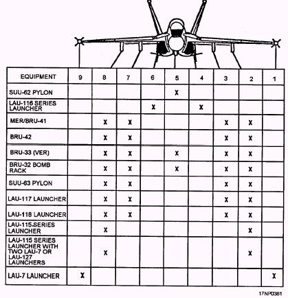
AN/ALE-39 Decoy Dispensing System The AN/ALE-39 decoy dispensing system gives an aircraft the capability to dispense chaff or flares. The decoy rounds are contained in two dispensers at the fuselage underside area. Control is supplied through the SMP. The system consists of the dispenser/ECM control panel, engine throttle lever grip assembly, left console DISP switch, AN/ALE-39 programmer, two AN/ALE-29A dispensers, MX-7721/ALE-29A dispenser housings, two 1874/ALE-39 sequencer switches, and the armament system's basic controls and components. Aircraft Armament Configuration Capabilities The basic armament configuration of the F/A-18 aircraft consists of LAU-116/A missile launchers, LAU-7 missile launchers, SUU-63/A pylons, SUU-62/A pylon, BRU-32/A bomb racks, and an M61A1 20-mm gun. The F/A-18 basic armament configuration can be reconfigured to accommodate a variety of weapons. Figure 15-19 shows the station configuration capabilities. If you want more information about authorized aircraft configurations and weapons loading, refer to A1-F18AA-TAC-000, volume 1, and A1-F18AA-TAC100, volume 2, NATOPS Tactical Manual. A general description of the F/A-18 armament systems and suspension or releasing equipment is contained in the Airborne Weapons/Stores Loading Manual, A1-F18AAA-LWS-000.
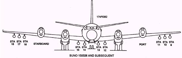
Figure 15-19.-F/A-18 aircraft station configuration capabilities. 15-19 ANTISUBMARINE WARFARE WEAPONS SYSTEMS LEARNING OBJECTIVE: Identify antisubmarine warfare weapons systems to include the basic system, the kill store system, the release and control system, the release and control systems checks, and weapons system maintenance. Antisubmarine warfare (ASW) is becoming a broad field. New developments are being made in submarine detection as well as in the tactical deployment of the equipment. The search stores (primarily sonobuoys), launched at precise intervals and locations and with the airborne electronics equipment, give accurate information in the detection of submarines. The kill stores consist of torpedoes, mines, bombs, rockets, and guided missiles. The basic ASW search and kill store system and its associated equipment are currently used in the P-3 and S-3 fixed-wing aircraft and the SH-60 rotary-wing aircraft. P-3 AIRCRAFT The basic P-3 (fig. 15-20) ASW weapons system consists of the equipment and accessories necessary for carrying and releasing kill stores and search stores. The system's equipment and accessories are discussed in the following text. Pilots Armament Control Panel The armament control panel provides the pilot with control of all kill and search stores. Pilots Search Stores Control Panel The pilots search stores control panel provides the pilot with operational control of the search stores system and provides a visual indication of the stores that are loaded and are available for release. TORP Presetter Panel This panel provides the controls and indicators for manual or automatic preset of Mk 46 or Mk 50 torpedoes. Weapon Release Switches The pilot and copilot have two switches for release of weapons other than missiles. Release of kill stores by the tactical coordinator is limited to bombs and torpedoes. Harpoon Aircraft Command Launch Control (Missile Control Panel) The missile control panel provides power application, controls, and displays for the Harpoon missile. The controls and displays are used for manually
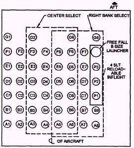
Figure 15-20.-P-3 ordnance stations. 15-20 defining missile selection or deselection, warhead fusing, target range and relative bearing, attack and seeker modes, and aircraft true airspeed and altitude inputs. Data Processor Computer (DPC) The data processor is a digital computer that provides the digital communications link between the Harpoon Aircraft Command Launch Control System (HACLCS) and the Harpoon missile. Armament Subsystems The following text provides general information on the aircraft armament subsystems and components. WEAPON SYSTEM.- The weapon system consists of the equipment and accessories necessary for loading, carrying, and releasing of kill and search stores. There are two subsystems, the armament (kill store) subsystem and the ordnance (search store) subsystem. The armament system refers to carriage and delivery of weapons or stores from the wing and bomb bay stations. The ordnance system refers to equipment used for carriage and delivery of search stores. A maximum of 8 bomb bay stations and 10 wing stations are available for carriage of weapons. There are 48 unpressurized sonobuoy launch tubes (SLT), 3 pressurized SLT, and 1 free-fall chute used with the search store system (fig. 15-21). BOMB BAY SYSTEM.- The bomb bay has a maximum of eight stations available at one time. The
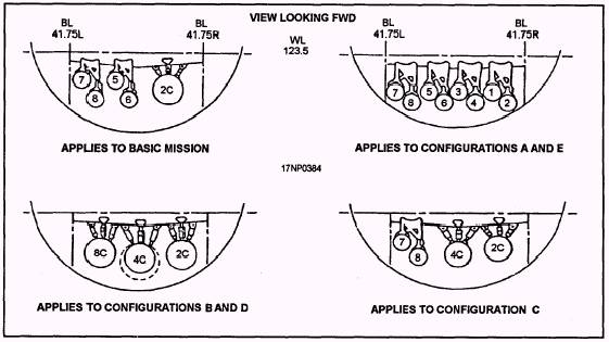
Figure 15-21.-P-3 sonobuoy launch tube arrangement. eight basic stations are arranged in two layers; odd numbered stations in the upper layer and even numbered stations in the lower layer. This configuration limits the release of weapons from the upper layer until the interfering weapon on the lower level has been released. Bomb racks are attached to removable pylons with two types of pylons (primary pylon and 1,000- to 2,000-pound class store pylon). Bomb rack installations are assigned a number or a number followed by a letter (fig. 15-22).
Figure 15-22.-Bomb bay weapons stations. 15-21 BOMB BAY CONFIGURATION.- There are four primary pylon assemblies (fig. 15-23) provided for carrying a maximum of eight bomb bay stores. The pylon consists of two BRU-12/A bomb racks mounted between two pylon ends. The BRU-12A bomb rack (fig. 15-24) is a modified MAU-38 series bomb rack. The BRU-12/A is interchangeable with the MAU-38, and installation, operation, maintenance, safety, and testing procedures are the same. There are three 1,000- or 2,000-pound class store pylon assemblies (fig. 15-25) provided for carrying a maximum of three 1,000- or one 2,000-pound class weapon. The pylon assembly consist of a BRU-14/A bomb rack with mounting adapters on station 4C. The Aero 1A adapters provide the BRU-14/A bomb rack with 30-inch suspension and load capabilities. Figures 15-26 through 15-31 show the various wing stations and bomb bay equipment configurations. For more information on the P-3 aircraft, refer to Airborne Weapons/Stores Loading Manual, NAVAIR 01-75PA-75. S-3 AIRCRAFT The S-3 (fig. 15-32) weapon control system has the units, panels, switches, logic circuits, interfaces, computer, and controls necessary for selecting, arming, and releasing the kill or search stores. Status lights indicate store selection errors and stores go or no-go status. Electrical jettison release systems are used to release or eject all the wing stores and all search stores of the S-3 aircraft. Armament Control Panel The armament control panel (ACP) provides the pilot with control for the manual delivery of forward-firing weapons, droppable stores, and the release of the SAR sonobuoy. |
|
|
|