Custom Search
|
|
  |
|
|
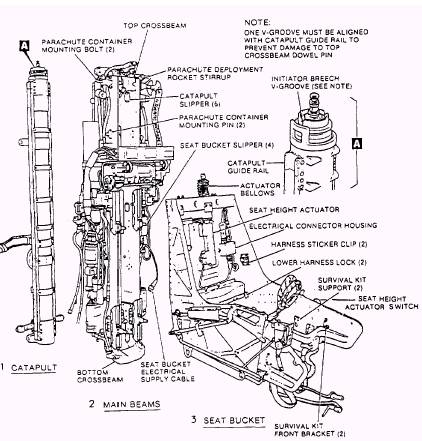
Each ejection seat, as installed in the aircraft, consists of five main assemblies. Each assembly is briefly described in the following paragraphs: (See figure 5-2.) 1. The catapult assembly is the means by which the ejection seat is secured to the aircraft structure during normal flight, and provides the initial force necessary to eject the seat from the aircraft during emergency conditions. The catapult assembly includes the barrel, ballistic latches, the piston, and the catapult manifold valve. 2. The main beams assembly includes the top and bottom crossbeams, top latch assembly, shoulder harness control handle, parachute deployment rocket motor, electronic sequencer, barostatic release unit, drogue deployment catapult, two multipurpose initiators, time-delay mechanism, two pitot assemblies, two ballistic manifolds, and two thermal batteries. 3. The seat bucket assembly includes the underseat rocket motor, lateral thrust motor, ejection control handle, safe/armed handle, leg restraint snubbers, emergency restraint release handle, shoulder harness control lever, seat height actuator switch, pin puller, and lower harness release mechanism. 4. The parachute assembly includes the parachute container and parachute canopy and drogue. 5. The seat survival kit assembly includes the lid assembly, emergency oxygen system, radio locator beacon, and rucksack assembly. Catapult Assembly The catapult assembly (figs. 5-3 and 5-4) secures the ejection seat to the aircraft structure
Figure 5-2.-Forward ejection seat main assemblies.
Figure 5-3.-Catapult assembly, forward seat. to ensure location of the catapult in the correct cockpit (fig. 5-5). An interference arm mounted on one of the guide rail brackets ensures that the correct main beams assembly is installed. A crossbeam secured to the barrel provides an anchorage point for the RH ballistic manifold quick-disconnect lanyard. The top end fitting of the barrel has a square aperture, the barrel latch, through which the plunger of the top latch mechanism fitted on the seat main beam protrudes when the seat is installed on the catapult. A guide bushing, fitted in the internal diameter of the top end fitting, is secured by three dowel screws; at the end of the catapult stroke, the dowel screws are sheared by the head of the piston striking the guide bushing. The piston then separates from the barrel, and the guide bushing remains on the piston (fig. 5-3). BALLISTIC LATCHES.- Two ballistic latches are attached to the bottom end fitting by studs and nuts. Each latch comprises a body, which is internally drilled to form a cylinder and contains a spring-loaded piston. When operated during the ejection sequence, gas pressure from within the catapult acts on the latch pistons,
Figure 5-4.-Ejection gun initiator (JAU-56/A) and catapult manifold valve. and provides the initial power for the ejection of the seat. The catapult consists of an outer barrel and an inner telescopic piston. The barrel is attached to the aircraft structure, and the piston and barrel are engaged at the top end by the top latch plunger installed in the main beams assembly. The catapult assembly is operated by explosive charges. Assembly operation is discussed later in this chapter. BARREL.- The barrel is a built-up structure consisting of a light alloy tube to which are permanently attached top and bottom end fittings. A housing situated towards the bottom end contains the secondary cartridge. Five brackets support two guide rails bolted on the outboard sides of the tube. The bottom end fitting incorporates the lower mounting bracket for attaching the catapult to the aircraft and studs for attachment of the ballistic latches. The upper mounting consists of a bracket clamped on the barrel towards the upper end. It incorporates an interference shoulder on one side
Figure 5-5.-Interference devices, forward and aft seats. overcoming the springs and retaining the multipurpose initiator lanyard spigots (fig. 5-3). PISTON.- The piston consists of a light alloy tube, attached to the lower end of which is a necked end fitted with piston rings to provide a gas seal between the piston and the barrel. At the upper end of the piston is a breech, into which the cartridge-activated initiator is inserted. The breech has a groove machined around its outer diameter, into which the plunger of the top latch mechanism on the seat main beams engages when the seat is installed on the catapult. A V-groove in the top of the breech engages a dowel on the seat top crossbeam when the seat is installed in the aircraft (fig. 5-3). CATAPULT MANIFOLD VALVE.- The catapult manifold valve provides an interface between the ejection seat and the catapult. The catapult manifold valve is mounted on the top of the catapult. The valve is locked onto the cartridge-activated initiator by a spring-loaded plunger and a retaining pin. The valve contains two inlet ports that connect the hoses from the time delays.
|
 
|
|
|