Custom Search
|
|
  |
|
|
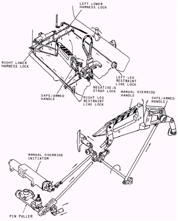
MANUAL OVERRIDE INITIATOR.- The manual override initiator (19) is mounted in a covered compartment in the lower aft right side of the seat bucket. A linkage connects the sear to the manual override handle. Pulling the handle releases the lower restraints. Full upward movement of the handle is prevented by the pin puller. However, during ejection, the pin puller is automatically retracted. This allows the manual override handle to pull the sear from the manual override initiator, which will override the automatic sequencing. This is accomplished by routing gas pressure to the time-release mechanism and the secondary cartridge of the drogue gun. PIN PULLER.- The pin puller (20) (fig. 6-20) (also shown in fig. 6-23) is located on the aft right side of the seat bucket. Full aft rotation of the manual override handle is prevented by the pin puller. A pin extended from the pin puller engages a slot in the manual override linkage. During the ejection sequence, gas pressure from the right seat initiator cartridge retracts the pin. ROCKET MOTOR.- The rocket motor (8) is attached to the bottom of the seat bucket. A rigid line from the rocket motor firing mechanism is connected to the inboard trombone fitting on the aft left side of the seat bucket. The trombone fitting interfaces with the rocket motor initiator, which is located on the main beam assembly. The rocket motor consists of a firing mechanism, igniter cartridge., manifold, four nozzles, and 17 propellant tubes. Gas pressure from the rocket motor initiator forces the firing mechanism into the igniter cartridge. The rocket motor ignites as the catapult nears the end of its extension and raises the ejection seat to a height sufficient for a safe ejection, even if the aircraft has zero speed and zero altitude. The rocket motor produces approximately 4,500 pounds of thrust for 0.25 second. The nozzles on the seat are positioned forward and outward. This positioning allows the thrust to pass close to the center of gravity of the ejection seat and pilot. SEAT SURVIVAL KIT.- The SKU-3/ A seat survival kit (fig. 6-24) consists of a two-piece bonded fiber glass container and a seat cushion. The kit is located in the seat bucket and functions as a seating platform for the pilot. The survival kit contains the torso harness attachments, locking system, retaining lanyard, survival equipment, radio beacon, and emergency oxygen. A bracket for insertion of the negative-g strap is mounted
Figure 6-23.- Manual override system
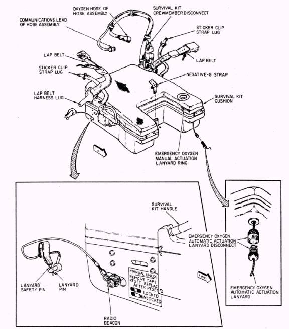
Figure 6-24.- SKU-3/ A survival kit on the forward lower half of the survival kit. The emergency oxygen system, located in the lid of the survival kit, consists of an emergency oxygen cylinder, reducer assembly, actuation assembly, and manifold assembly. A lanyard and quick-disconnect fitting provide automatic actuation of the emergency oxygen system during ejection. If the aircraft oxygen system fails, emergency oxygen is available by actuating the emergency oxygen manual release. The release is a green ring located on the forward left side of the survival kit. A mounting is provided for the radio locator beacon and lanyard. The lanyard actuates the beacon upon ejection. LEG RESTRAINTS.- Two leg restraint line snubbing units and lines are mounted to the for-ward structure of the seat bucket. The leg restraint lines are secured in locks located on the inboard sides of the seat bucket. The leg restraints secure the pilot's legs to the seat during ejection. They consist of two adjustable leg garters, a restraint line, and a snubber unit for each leg. One garter is worn on the thigh and one on the lower leg. The restraint lines are routed through the garter rings and the snubber unit. One end of each restraint line is secured to the cockpit floor and the other is secured to the seat by a releasable pin. During ejection, the slack in each line is taken up and the leg lines separate at the tension rings. When the pilot and seat separate, the pins are normally released by the time-release mechanism. They may also be released by pulling the manual override handle. Both the lower garter and thigh garter contain a quick-release buckle. The leg restraint line runs through a ring that is disconnected by the buckle. This permits the pilot to exit the air-craft while wearing both the upper and lower garters. The lower restraint mechanism locks are located in the lower aft portion of the seat bucket. These locks are connected by a cross shaft and linkage to the leg restraint line locks and the negative-g strap lock. The operation of SJU-5/ A system components and subsystems is discussed in the following paragraphs.
|
 
|
|
|