Custom Search
|
|
  |
|
|
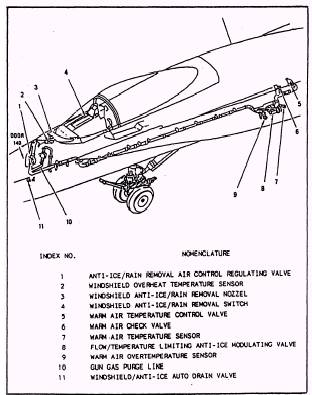
Aviation Structural Mechanic E 2 CHAPTER 1 UTILITY SYSTEMS Terminal Objectives: Upon completion of this chapter, you will have a working knowledge of bleed-air, liquid cooling, windshield wiper/ washer, rain repellant, fire extinguishing, and thermal radiation protection utility systems. The utility systems of an aircraft provide an additional measure of flight safety, pilot comfort and convenience, and contributes to the overall mission capability of the aircraft. Those utility systems of primary concern to you that are in-cluded in this chapter are the various bleed-air, liquid cooling, fire extinguishing, and thermal radiation protection systems. AUXILIARY BLEED-AIR SYSTEMS Learning Objective: Recognize the operating principles and functions of auxiliary bleed-air utility systems. An aircraft's auxiliary bleed-air system furnishes supply air for air-conditioning and pressurization systems, as well as for electronic equipment cooling, windshield washing, anti-icing, and anti-g systems. The bleed-air system also pressurizes fuel tanks, hydraulic reservoirs, and radar waveguides on several types of aircraft. The air for these systems is tapped off downstream of the air-conditioning turbine before any cooling takes place, or at various points within the air-conditioning system. Bleed air for these systems can range Up to 400 F (205 C) at pressures of up to 125 psi. Because each type of aircraft has a somewhat different approach in system design, temperatures, and pressures, the systems and components in this manual will be representative of types found throughout the Navy. Under no circumstances should this manual be regarded as the final source of technical data used to perform aircraft maintenance. For the most up-to-date information, refer to the proper Maintenance Instructions Manual (MIM) for the system concerned. WINDSHIELD ANTI-ICE/ RAIN REMOVAL SYSTEM This system is designed to provide a means of maintaining visibility from the aircraft. The F-18 windshield anti-ice/ rain removal system is typical of systems found in jet air-craft. This system supplies controlled temperature air from the air cycle air-conditioning system (ACS) to provide airflow over the external surface of the windshield for rain removal and windshield anti-icing. System Control The system is electrically controlled and pneumatically operated. There are three modes of operation controlled by the windshield anti-ice/ rain removal switch. 1. OFF. The anti-ice/ rain removal air control regulating valve is closed, and there is no airflow over the windshield. 2. RAIN. Low-pressure (2.5 psig) and low-volume (20 lbs/ min) air at 250 F directed across the windshield through the anti-ice/ rain removal nozzle. 3. ANTI-ICE. High-pressure (16 psig) and high-volume (57 lbs/ min) air at 250 F directed across the windshield through the anti-ice/ rain removal nozzle. Low Limit Temperature Control Refer to figure 1-1 for component location. The supply air temperature is controlled to a lower limit of 290 F by the warm air temperature control valve and the warm air temperature sensor. If air temperature supplied by the air cycle ACS exceeds 290 F, the warm air temperature control valve will close and stop airflow from the bleed-air system. The 290 F supply temperature is cooled as it passes through the ducting to approximately 250 F at the nozzle. The 250 F temperature provides enough heat for windshield deicing, yet is low enough to prevent damage to the windshield. High Limit Temperature Control The warm air overtemperature sensor actuates when supply air temperature reaches 375 25 F and signals the flow/ temperature limiting anti-ice modulating valve. This valve regulates airflow supply, which reduces bleed airflow through the primary heat exchanger and reduces airflow
Figure 1-1.- Windshield Anti-ice and rain removal system component locator. supply temperature to below 375 25 F. The combined action of the warm air overtemperature sensor and flow/ temperature limiting anti-ice modulating valve also provides the required protection against a defective warm air temperature control valve. Anti-Ice/ Rain Removal Air Control Regulating -Valve The anti-ice/ rain removal air control regulating valve completes the final pressure regulation and flow control before airflow reaches the anti-ice/ rain removal nozzle. The valve regulates pressure and flow rate depending on the position of the windshield anti-ice/ rain removal s w i t c h. Windshield Overheat Temperature Sensor The windshield overheat temperature sensor, located downstream of the anti-ice/ rain removal air control regulating valve, is a temperature-activated switch, which opens if airflow temperature reaches 290 5 F. It closes when airflow temperature drops to 280 5 F. When the switch is open, a ground is lost to the signal data converter and the signal data computer, which causes the digital display indicator to display a (WDSHLD HOT) caution message. ANTI-G SYSTEM The anti-g system supplies and controls the flow of air pressure to the pilot's anti-g suit to compensate for forces exerted upon the human body during flight conditions. This system is designed to accomplish the following: 1. Provide protection against grayout, blackout, and unconsciousness 2. Alleviate fatigue and decreased mental alertness, which may result from repeated accelerations below the blackout level 3. Provide a method by which the pilot may relieve leg stiffness and physical tension during flight 4. Provide the pilot with a physical indication of the approximate acceleration to which the air-craft is being subjected |
 
|
|
|