Custom Search
|
|
  |
|
|
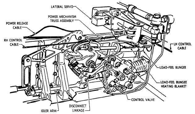
Aileron Control System The aileron control system, shown in figure 9-8, is equipped with a power mechanism that provides hydraulic power to operate the ailerons. If hydraulic power fails, the mechanism can be disconnected, placing the system in complete manual operation. Movement of the aileron control system begins when the control stick in the cockpit moves left or right. When the stick is moved, cables connected to the bell crank in the control stick housing are moved to operate the sector on the power mechanism. With the actuation of the sector, the power mechanism operates, transferring the movement to the mechanical linkage that operates the ailerons. The aileron power mechanism consists of two control valves, a dual-chambered hydraulic power cylinder, cable sectors, and a system of latches and related cranks. Linkage connects the control valves in tandem. The flight control hydraulic system powers one valve, and the other is powered by the utility hydraulic system.The power cylinder is a single tandem cylinder, composed of four chambers with pistons connected to a common shaft. Each of the two control valves operates on that portion of the power cylinder to which it is associated. Both hydraulic systems operate simultaneously, and each delivers 3,000-psi pressure to the mechanism. If one hydraulic system should fail, the other system will supply enough power to operate the ailerons at reduced hinge movement.When the control stick moves, the control cables move the power mechanism sector. Through linkage, the sector operates the control valves, which direct hydraulic fluid to the power cylinder. The cylinder actuating shaft, which is connected to the power crank through a latch mechanism, operates the power crank. The crank moves the push-pull tubes, which actuate the ailerons. In the event of complete hydraulic power failure, a handle in the cockpit maybe pulled to disconnect the latch mechanisms from the cylinder. When the handle is pulled, it places this particular aileron system in complete manual operation. In manual operation, the power cylinder is disconnected from the cable sector, causing the control stick to manually move the ailerons at a reduced rate.The lateral control system incorporates a load-feel bungee, which serves a dual purpose. See figure 9-9. The bungee provides an artificial feel and centering device for the aileron system. It is interconnected between the aileron system and the aileron trim system. Energizing the aileron trim actuator moves the bungee operating the power mechanism, which repositions the aileron control system to a new neutral position.In normal operation of the control system, when the control stick is actuated left or right, the power mechanism compresses the bungee. The compressed bungee returns the stick to the neutral position upon release of the stick.
|
|
|
|