Custom Search
|
|
  |
|
|
Ram Air Turbine-Driven System In this type of emergency hydraulic system, ram air is used to turn the blades of a turbine that, in turn, operates a hydraulic pump. The turbine and pump assembly is generally installed on the inner surface of a door installed in the fuselage. The door is hinged, allowing the assembly to be extended into the slipstream by pulling a manual release in the cockpit.
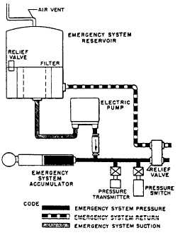
Figure 7-40.Schematic diagram of typical emergency power system (electric-motor driven).Figure 7-41 shows a typical ram air unit. This type of emergency system is intended for use only when normal hydraulic pumps are completely inoperative. Because of differences in system designs, aircraft emergency system operating pressures will differ from one aircraft to another. The ram air turbine system shown in figure 7-41 provides a means for emergency hydraulic and electrical power when the normal aircraft hydraulic system has failed. The turbine-driven hydraulic pump supplies fluid under pressure to the primary flight controls as well as to an emergency hydraulically driven alternator. The turbine system shown in figure 7-42 consists of a dropout governor-controlled turbine, a hydraulic
The turbine is maintained in the fully extended position by a hydraulic lock in the turbine actuator. When the RAM AIR TURBINE RETRACT button switch is depressed, electrical power is supplied to the solenoid-operated turbine retract control valve. Hydraulic pressure from the hydraulic power system is ported to the retract side of the turbine actuator (fig. 7-42) through a restrictor, which controls the retract speed. As the turbine door reaches the closed position, the spring-loaded hook-type lock is caromed up until it drops over the roller, locking the door closed. When the button switch is released, electrical power is removed from the control valve and the retract side of the actuator is repressurized, thus completing the retract cycle. |
|
|
|