Custom Search
|
|
  |
|
|
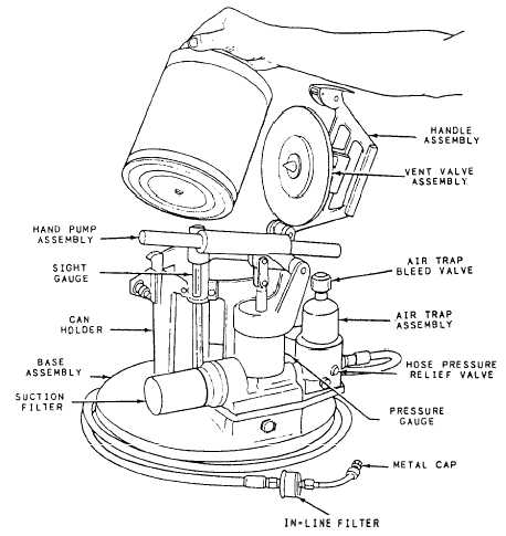
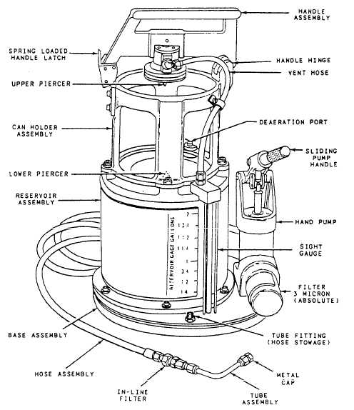
SPECIFIC SUPPORT EQUIPMENT Several approved types of fluid-dispensingequipment are available for use in servicing hydraulic systems. The primary difference between the types of equipment is their fluid-holding capacity. As you read this section, refer to table 4-4, which lists the different types of fluid-dispensing equipment. Do not use any fluid servicing equipment other than that listed in the table; they are not authorized unless specifically approved for use by the aircraft controlling custodian, cognizant engineering activity, NADEPs, or NAV-AIRSYSCOM. All SE must be fitted with 3-micron (absolute) filtration in the fluid discharge line. SE construction must not expose fluid contents to either internally generated or external contamination. Model H-250-1 Hydraulic Servicing Unit The Model H-250-1 hydraulic servicing unit is a 1-gallon servicing unit (fig. 4-8). It provides a way of servicing systems by hand-pumping filtered fluid directly from the original container without exposing the fluid to open air or to other atmospheric contamination. The unit accepts the standard, l-gallon container, which, when installed, serves as a reservoir. The servicing unit has 3-micron (absolute) filtration to prevent particulate contamination of a system by new fluid that may not meet the prescribed cleanliness prior to packaging. While contamination in new fluid is rare, its occurrence has been reported.
The original fluid container serves as a reservoir for the H-250-1 servicing unit. This container is not opened until it is placed in the unit, and the handle assembly pressed into a locked position. When the handle is locked, the can is sealed into the unit by cleanly piercing its top and bottom. This action automaticallyy destroys the cans potential for reuse. The H-250-1 servicing unit is equipped with a top piercing pin, which is drilled to provide the can with atmospheric venting through a 5-micron filter. Also, it has a check valve to minimize airborne particulate and moisture contamination. The lower piercing pin is drilled so the hydraulic fluid can reach the pump through a passage in the base casting and a 3-micron filter. The filter is a nonbypass type. When it becomes loaded, the unit is inoperative. The filter housing is designed so that the pump wont operate if a filter element has not been installed. A pressure gauge, an air trap, and a manual air bleed valve are attached directly to the pump assembly base. The air trap automatically removes any air present in the fluid at the pump chamber and retains it in a separate trap. Air collected in the trap is vented from the unit by manually operating a spring-loaded, air bleed valve. The H-250-1 servicing unit has an 8-foot service hose that is equipped with a 3-micron, in-line filter connected at the discharge end, which prevents reverse flow contamination through the hose. There are several types of disconnect fittings on the reservoir service units of naval aircraft. There are no mating fittings provided with the unit. Each activity must procure and install the disconnect fitting required for compatibility with the aircraft supported. Both male and female fittings are procured so that half can be installed on the hose end and half on the bracket provided. The bracket-mounted fittings will provide a contamination-free means of stowing the discharge end of the service hose when the equipment is not in actual use. |
 
|
|
|