Custom Search
|
|
  |
|
|
Preinstallation Inspection Prior to each use, or once a month as in the case of emergency handling slings, a complete visual inspection of the wire rope, fabric or webbing, structural steel or aluminum, and chain slings must be performed.WARNING Slings failing to pass the inspections, or slings suspected of having been used during hoisting operations beyond the rated capacity of the sling, will not be used under any circumstance. Unserviceable slings are forwarded to the applicable Aircraft Intermediate Maintenance Department for further analysis and disposition.
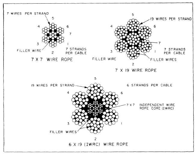
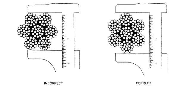
WIRE ROPE. To assist in understanding various inspection criteria for wire rope, a basic knowledge of wire rope construction is required. Each individual cylindrical steel rod or thread is known as a wire. Each group of wires twisted together forms a strand. A group of strands twisted around a central core is known as a wire rope or cable. A filler wire is a wire used to fill the voids between wires in a strand and between strands in a wire rope. They provide stability to the shape of the strand or wire rope with little strength contribution. Wire rope construction is designated by two numbers. The first being the number of strands in a cable, and the second being the number of wires in each strand. The following wire rope constructions are used in the fabrication of aircraft hoisting slings. See figure 3-23. A 7 x 7 wire rope consists of six strands of seven wires each twisted around a single core strand of seven wires. The 7 x 7 construction is used on wire ropes measuring 1/16 and 3/32 inch in diameter. Similarly, 7 x 19 wire rope is constructed with six strands of 19 wires each twisted about a core strand also containing 19 wires. The 7 x 19 wire ropes measure from 1/8 to 3/8 inch in diameter. A 6 x 19 independent wire rope core (IWRC) cable consists of six strands each containing 19 wires twisted about a core that is of a 7 x 7 construction. The 6 x 19 (IWRC) wire rope measures from 7/16 to 1 1/2 inches in diameter. During the inspection of a wire rope, the measurements of the diameter and lay length (pitch length) often lead to confusion. The diameter and lay length are defined as follows:1. Diameter, The diameter of a wire rope is the diameter of a circle circumscribed around the cable
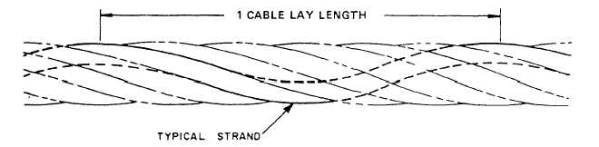
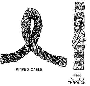
cross section. Figure 3-24 shows the proper method of measuring the diameter of a wire rope.2. Lay Length. The distance, parallel to the axis of the cable, in which a strand makes one complete turn about that axis is known as the lay length or pitch length. Figure 3-25 shows the lay length of a wire rope. Wire rope cables are visually inspected for knots, fraying, stretching, abrasions, severe corrosion, and other signs of failure. Of particular importance is the detection of a cable in which a kink has been pulled through in order to straighten the cable. The resultant deformation is known as a bird cage. See figure 3-26. In such a case, the sling should be discarded. The presence of one or more broken wires in one rope lay length or one or more broken wires near an attached fitting is cause for replacement. If a broken wire is the result of corrosion or if the cable is excessively corroded, the cable must not be used regardless of the
number of broken wires. Replace cables exhibiting rust and development of broken wires in the vicinity of attached fittings. Replace wire ropes evidencing bulges, core protrusions, or excessive reductions in rope diameter. FABRIC OR WEBBING. Fabric or webbing straps must be visually inspected for cuts, holes, severe abrasions, mildew, dry rot, broken stitches, frays and deterioration. Deterioration may be caused by contact with foreign materials such as oil, fuel, solvents, caustic fluids, dirt, and lye. The existence of any of the above conditions renders the sling unserviceable. Twists, knots, and similar distortions must be corrected before use.STRUCTURAL STEEL OR ALUMINUM. Visually inspect all terminals, shackles, lugs, and structural members for misalignment, wear, corrosion, deformation, loosening, slippage, fractures, open welds, pitting, and gouges. Examine slides and screw adjusters for burrs, misalignment, and ease of operation. Inspect sling attachment bolts and pins for elongation, wear, deformed threads, and other signs of imminent failure.CHAINS. Chains will be visually inspected for stretched links, wear, gouges, open welds, fractures, kinks, knots, and corrosion. Chain attachment fittings and adjusters will be examined for security, wear, corrosion and deformation. |
|
|
|