Custom Search
|
|
  |
|
|
BULKHEADS. Any major
vertical structural member of a
semimonocoque fuselage, hull, or float may
be considered a bulkhead. Bulkheads serve to maintain
the required external contour at the station
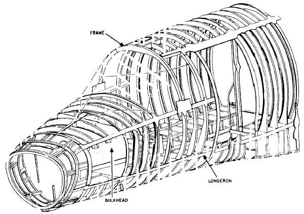
Figure 13-71.-Rib repair by patching. where they are located. They also give rigidity and strength to the structure.Bulkhead construction is similar to that used for wing ribs. It consists of a web reinforced by angle stiffeners. The web is attached to the skin by formed flanges or extruded angles, which serve as capstrips. Non-watertight bulkheads may have lightening holes, and most bulkheads are cut out to give clearance for stringers. The stringers are usually attached to the bulkhead by angle clips.The repair of the web and formed flange of a bulkhead is similar to that used for the rib web and flange repair shown in figure 13-71; however, the structural repair manual must be consulted for specific information on the repair of a particular bulkhead.When damage to the web is a crack, dent, or small hole, it may be repaired in the same manner as fully stressed skin. Buckled webs may be repaired by riveting an angle reinforcement over the buckled area, provided the bulkhead is not otherwise distorted. Sheet metal used for repairs near a flanged lightening hole should be formed with a 90-degree flange to provide additional stiffening.LONGERONS. Most aircraft fuselages are constructed in sections and are of the semimonocoque design. A longeron is a fore-and-aft member of the fuselage or nacelle and is usually continuous across a number of points of support, such as frames and bulkheads. The longerons, along with the stringers, are the major load-carrying members and stiffeners. Figure 13-72 shows the location of the major members of a semimonocoque design forward fuselage. In case it becomes necessary to repair a longeron, review the section on stringer repair and follow the same procedure.RECOMMENDED READING LIST NOTE: Although the following References were current when this TRAMAN was published, their continued currency cannot be assured. Therefore, you need to be sure that you are studying the latest revision.Use and Care of Hand Tools and Measuring Tools, NAVEDTRA 12085, Naval Education and Training Program Management Support Activity, Pensacola, Florida, 1992.
Figure 13-72.Forward fuselage (semimonocoque). Blueprint Reading and Sketching, NAVEDTRA 10077-F1, Naval Education and Training Program Management Support Activity, Pensacola Florida, July 1988, Chapters 1, 8, and 9.Aerospace MetalsGeneral Data and Usage Factors, Headquarters, Washington, D.C., November 1967, Change 19, September 1989. General Manual for Structural Repair, NAVAIR 01-1A-1, Commander, Naval Air Systems Command, Washington, D.C., 15 July 1969, Change 11, 15 August 1989.Structural Hardware, NAVAIR 01-1A-8, Com-Command mander, Naval Air Systems Command, Washington, D.C., 1 January 1991. |
|
|
|