Custom Search
|
|
  |
|
|
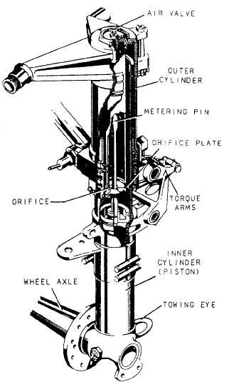
SHOCK STRUTS Shock struts are self-contained hydraulic units. They carry the burden of supporting the aircraft on the ground and protecting the aircraft structure by absorbing and dissipating the tremendous shock of landing. Shock struts must be inspected and serviced regularly for them to function efficiently. This is one of your important responsibilities.Each landing gear is equipped with a shock strut. In addition to the landing gear shock struts, carrier aircraft are equipped with a shock strut on the arresting gear. The shock struts primary purpose is to reduce arresting hook bounce during carrier landings.Because of the many different designs of shock struts, only information of a general nature will be included in this chapter. For specific information on a particular installation, you should refer to the applicable aircraft MIM or accessories manual.A typical pneumatic/hydraulic shock strut (metering pin type) is shown in figure 12-8. It uses compressed air or nitrogen combined with hydraulic fluid to absorb and dissipate shock, and it is often
Figure 12-8.Landing gear shock strut (metering pin type). referred to as the "air-oil" type strut. This particular strut is designed for use on the main landing gear. As shown in the illustration, the shock strut is essentially two telescoping cylinders or tubes, with externally closed ends. When assembled, the two cylinders, known as cylinder and piston, form an upper and lower chamber for movement of the fluid. The lower chamber is always filled with fluid, while the upper chamber contains compressed air or nitrogen. An orifice (small opening) is placed between the two chambers. The fluid passes through this orifice into the upper chamber during compression, and returns during extension of the strut.Most shock struts employ a metering pin similar to that shown in figure 12-8 to control the rate of fluid flow from the lower chamber into the upper chamber. During the compression stroke, the rate of fluid flow is not constant, but is controlled automatically by the variable shape of the metering pin as it passes through the orifice.
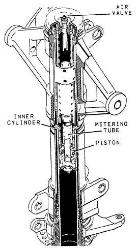
Figure 12-9.Landing gear shock strut (metering tube type). On some types of shock struts now in service, a metering tube replaces the metering pin, but shock strut operation is the same. An example of this type of shock strut is shown in figure 12-9.Some shock struts are equipped with a dampening or snubbing device, which consists of a recoil valve on the piston or recoil tube. The purpose of the snubbing device is to reduce the rebound during the extension stroke and to prevent a too rapid extension of the shock strut, which would result in a sharp impact at the end of the stroke.The majority of shock struts are equipped with an axle that is attached to the lower cylinder to provide for tire and wheel installation. Shock struts not equipped with axles have provisions on the end of the lower cylinder for ready installation of the axle assembly. Suitable connections are also provided on all shock struts to permit attachment to the aircraft.A fitting, which consists of a fluid filler inlet and a high-pressure air valve, is located near the upper end of
Figure 12-10.Nose gear shock strut. each shock strut to provide a means of filling the strut with hydraulic fluid and inflating it with air or nitrogen.A packing gland designed to seal the sliding joint between the upper and lower telescoping cylinders is installed in the open end of the outer cylinder. A packing gland wiper ring is also installed in a groove in the lower bearing or gland nut on most shock struts to keep the sliding surface of the piston or inner cylinder free from dirt, mud, ice, and snow. Entry of foreign matter into the packing gland will result in leaks. The majority of shock struts are equipped with torque arms attached to the upper and lower cylinders to maintain correct alignment of the wheel.Nose gear shock struts are provided with an upper centering cam that is attached to the upper cylinder and a mating lower centering cam that is attached to the lower cylinder. See figure 12-10. These cams serve to line up the wheel and axle assembly in the straight-ahead position when the shock strut is fully extended. This prevents the nosewheel from being cocked to one side when the nose gear is retracted, preventing possible structural damage to the aircraft. These mating cams
Figure 12-11.Shock strut operation. also keep the nosewheel in a straight-ahead position prior to landing when the strut is fully extended. Some nose gear shock struts have the attachments for installation of an external shimmy damper, which is discussed later in this chapter.Nose and main gear shock struts are usually provided with jacking points and towing lugs. Jacks should always be placed under the prescribed points. When towing lugs are provided, the towing bar should be attached only to these lugs.All shock struts are provided with an instruction plate that gives, in a condensed form, instructions relative to the filling of the strut with fluid and inflation of the strut. The instruction plate also specifies the correct type of hydraulic fluid to use in the strut. The plate is attached near the high-pressure air valve. It is of the utmost importance that you always consult the applicable aircraft MIMs and familiarize yourself with the instructions on the plate prior to servicing a shock strut with hydraulic fluid and nitrogen or air. Figure 12-11 shows the inner construction of a shock strut and the movement of the fluid during compression and extension of the strut. The com-pression stroke of the shock strut begins as the aircraft hits the ground. The center of mass of the aircraft con-tinues to move downward, compressing the strut and sliding the inner cylinder into the outer cylinder. The metering pin is forced through the orifice, and by its variable shape, controls the rate of fluid flow at all points of the compression stoke. In this manner, the greatest possible amount of heat is dissipated through the walls of the shock strut. At the end of the downward stroke, the compressed air or nitrogen is further compressed, limiting the compression stroke of the strut. If there is an insufficient amount of fluid and/or air or nitrogen in the strut, the compression stroke will not be limited, and the strut will "bottom" out, resulting in severe shock and possible damage to the aircraft. The extension stroke occurs at the end of the compression stroke, as the energy stored in the compressed air or nitrogen causes the aircraft to start moving upward in relation to the ground and wheels. At this instant, the compressed air or nitrogen acts as a spring to return the strut to normal. At this point, a snubbing or dampening effect is produced by forcing the fluid to return through the restrictions of the snubbing device (recoil valve). If this extension were not snubbed, the aircraft would rebound rapidly and tend to oscillate up and down because of the action of the compressed air. A sleeve, spacer, or bumper ring incorporated in the strut limits the extension stroke. |
|
|
|