Custom Search
|
|
  |
|
|
LANDING GEAR SYSTEMS
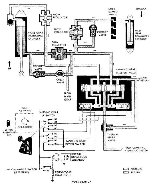
OPERATION Learning Objective: Identify the operational and troubleshooting procedures for landing gear systems.Landing gear systems on naval aircraft, as stated earlier, are similar in design. Most aircraft equipped with the tricycle-type, retractable landing gear have two systems of operation, normal and emergency.NORMAL SYSTEM The normal system of a "typical" landing gear system is described because many components used in different landing gear systems are similar. Figure 12-2 is a schematic that shows the fluid flow in the nose gear up cycle. This system contains a selector valve, flow regulators, priority valves, check valve, actuating cylinders, and the necessary hydraulic tubing that routes hydraulic fluid to and from the required components.
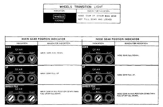
Figure 12-2.Nose gear up cycle schematic. When the landing gear handle is in the UP position, a circuit is completed from the landing gear handle circuit breaker, through the landing gear up switch, to the selector valve. The selector valve is electrically positioned to direct pressure into the landing gear up lines and to vent the down lines to return. Fluid flows from the selector valve, through a flow reguIator to the up side of the nose gear cylinder. Fluid also flows through another flow regulator to the down lock cylinder. The down lock cylinder disengages the down lock, and the nose gear cylinder starts to raise the nose gear. As the gear is raised, the nose gear doors are closed by mechanical linkage. When the gear is fully retracted, the up lock mechanism engages the nose gear to lock it in the up position. The up lock mechanism is mechanically actuated through linkage connected to the nose gear.As soon as the down lock mechanism is disengaged and the gear starts to retract, the pilots position indicator displays change from a wheel to a barber pole, and the transition light on the landing gear control panel comes on. As soon as the gear is up and locked, the transition
Figure 12-3.Landing gear warning and position indicator. light goes out and the position indicator changes from a barber pole to UP, as shown in figure 12-3. When the landing gear is down and locked, wheels appear on the indicator. |
|
|
|