Custom Search
|
|
  |
|
|
TIMING BOBBIN CASE OPENER.- To set the bobbin case opener, turn the balance wheel toward the operator until the lower timing mark on the needle bar is barely visible below the needle bar frame on its upward stroke. Tip the machine back and loosen the two Allen screws in the bobbin case opener drive gear; then line up the timing marks by turning the opener shaft with a screwdriver. The timing marks are located as follows: one on the flange of the opener, and the other on the hook saddle (fig. 9-35). Adjust the opener so it lightly touches the bobbin case and turns it enough to make a sufficient opening for a free passage of thread between the bobbin case stop finger and the throat plate. Tighten the screws in the bobbin case opener drive gear. RAISING OR LOWERING THE FEED DOG.- To raise or lower the feed dog, remove
Figure 9-36.-Hook saddle assembly showing bobbin case raceway oil reservoir.
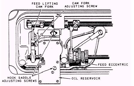
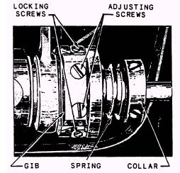
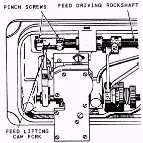
Figure 9-38.-The feed eccentric. CAUTION LOCKING SCREWS MUST BE LOOSENED BEFORE ATTEMPTING TO LOOSEN ADJUSTING SCREWS. RETIGHTEN THE LOCKING SCREWS AFTER ADJUSTMENT IS MADE. The feed eccentric collar may be moved to the right or left to change spring tension, but it is ordinarily set flush with the hub of the eccentric body. CHANGING THE LENGTH OF THE STITCH.- TO change the length of stitch, stop the machine. Turn the balance wheel, by hand, toward the operator until the button drops (clicks), then turn the machine pulley until the number representing the desired stitches per inch is lined up properly and then release the button. CAUTION DISENGAGE THE BUTTON BEFORE ATTEMPTING TO SEW. DO NOT ENGAGE THE BUTTON WHILE THE MACHINE IS IN OPERATION. Removing Components To remove the hook, takeoff the presser foot, throat plate, and feed dog; then loosen the two the throat plate and clean all lint and dirt from between the grooves and teeth of the feed dog. Tip the machine back and turn the balance wheel toward the operator until the feed dog is in its highest position. Loosen the screw in the feed lifting cam fork and raise or lower the dog as desired; then retighten the screw. A properly set feed dog will show a full tooth above the throat plate when at its highest position. After adjusting the feed dog, check to see that the needle is properly set in the hole in the feed dog. If adjustment is needed, loosen the pinch screws in the feed driving rock frame, and set the needle so that when it is all the way down, it will be slightly forward of center in the hole. Retighten the pinch screws. The feed adjustment points are illustrated in figure 9-37. ADJUSTING FEED ECCENTRIC.- The feed eccentric (fig. 9-38) may occasionally need adjustment to remove play caused by wear of the gib, or by looseness between the feed eccentric and the eccentric body. To adjust the gib, loosen the two locking screws, then turn inward on the adjusting screws until all play is eliminated and the eccentric fits in the slot properly.
Figure 9-37.-Feed adjustment for the 211 W 151 sewingmachine. Allen screws in the hub of the hook and lift the hook off the hook shaft. To remove the bobbin case from the hook assembly, loosen the hook gib screws, lift off the gib, and then lift out the bobbin case. Removing the Arm Shaft Connection Belt When the arm shaft connection belt is disconnected for any reason, the machine will be completely out of time. Therefore, the needle should be removed before removing the belt to prevent damage. To remove the belt, slide it off the lower belt pulley, loosen the screws in the machine pulley, and remove the pulley and ball bearing, which come out through the end of the arm. Replace the belt by reversing this procedure. Remove the end play from the shaft by lightly setting the setscrews and tapping the balance wheel into position with the palm of the hand and then securely setting the setscrews. Place the belt over the upper belt pulley and line up the timing marks on the lower belt pulley and on the bed of the machine. While holding the lower belt pulley in position, turn the balance wheel toward the operator's position until the thread take-up lever is at its highest position, then slide the belt onto the lower belt pulley. The arm shaft connection belt and the lower belt pulley are illustrated with the safety clutch in figure 9-32. CAUTION DO NOT TAMPER WITH THE SAFETY CLUTCH. ITS TORQUE IS PRESET AT THE FACTORY. Lubrication The hook saddle is equipped with an oil reservoir (fig. 9-36), which contains oil to be pumped to the bobbin case raceway. The flow of this oil is controlled by a control valve screw located just aft of the bobbin case opener in the hook saddle. For more oil, turn the valve screw clockwise; counterclockwise for less oil. CAUTION DO NOT ADJUST FLOW OF OIL WITHOUT FIRST LOOSENING THE LOCKING SCREW LOCATED ON THE SIDE OF THE HOOK SADDLE JUST ABOVE THE CAM SHAFT GEAR. AFTER ADJUSTING THE CONTROL VALVE SCREW FOR PROPER FLOW, RETIGHTEN THE LOCKING SCREW. |
|