Custom Search
|
|
  |
|
|
AN/PRC-90 RADIO SET The AN/PRC-90 (fig. 5-8) radio set is a dual channel, battery-powered, personal emergency rescue device used principally for two-day voice or MCW (modulated continuous wave, which is used to send Morse code signals) communications between a downed aircrewman and a rescue aircraft. The radio transmits either voice. tone (MCW), or swept-frequency homing beacon
Figure 5-8.-AN/PRC-90 controls and indicators. signals to guide rescue aircraft to the downed aircrewman. Although the PRC-90 is a line-ofsight communications device, it has a voice range under ideal conditions of 60 nautical miles to aircraft operating at 10,000 feet. The automatic direction finder has a range of 50 nautical miles and atone (code signal) range of 80 nautical miles to aircraft operating at an altitude of 10,000 feet. Batteries The batteries are tested by using Test Set TS 2530/UR. Batteries are considered to have a maximum shelf life of 36 months from the date of manufacture. This shelf life is based upon a storage temperature of 70 'F. If the temperature increases, their storage life is shortened. For example, if the temperature reaches 130 'F, the storage life can be reduced to as short as 1 month. When you are in an activity that uses this battery, you should refer to NAVAIR 16-30PRC 90 for the most current shelf life information. Operating Procedure Refer to table 5-2 for the functions of each control on the PRC-90. The set is operated as follows: 1. Free the antenna from its stowed position by pulling its end from the retaining ring or band Table 5-2.-Operating Controls and Indicators
Table 5-2.-Operating Controls and Indicators-Continued
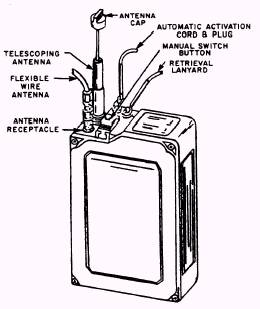
as appropriate. The antenna snaps into an upright position. Fully extend all five telescopic sections of the half-wave antenna by grasping it by its tip and pulling outward.2. Set the function switch to the mode of operation that you want. The function switch is set by rotating the thumb knob on the right-hand side so that the arrow points to the mode selected. The function switch is detented and clicks into each position. Rotate the knob down one click (from OFF) for VOICE/MCW 243.0 operation, or two clicks for BCN 243.0 operation. For VOICE 282.8 operation (secondary channel), push the button with the arrow and rotate the function switch knob up one click.3. For voice operation, hold the radio set and adjust the VOL control. To transmit, push down the PRESS TO TALK button and speak directly into the TALK microphone.4. If guard channel steady-tone transmission or Morse code operation is desired, set the function switch to VOICE/MCW 243.0. Depress the MCW button to transmit the tone. Listen for the sidetone in the LISTEN speaker or earphone while the MCW button is depressed. This sidetone indicates proper transmitter operation.5. For guard channel beacon operation, set the function switch to BCN 243.0. The transmitter continuously sends the swept-tone beacon signal at this setting. Listen for the sidetone as an indication of proper operation. In the beacon mode, the sidetone is a chirping sound.NOTE: Since the transmitter is keyed automatically in the beacon mode, and since continuous transmission may be needed for a prolonged period of time, the AN/PRC-90 may be placed upright on a flat surface. It will then transmit automatically.AN/URT-33A BEACON SET RADIO The Beacon Set Radio, AN/URT-33A (figs. 5-9 and 5-10), is an emergency radio beacon transmitter that, when properly actuated, transmits a tone-modulated radio frequency signal on the emergency guard frequency of 243.0 MHz. Although the AN/URT-33A was designed to be placed into a parachute pack, the Navy normally places the beacon radio into the seat pan (RSSK) or life rafts. Instructions for properly rigging the AN/URT-33A can be found in NAVAIR 13-1-6.1.The AN/URT-33 radio has two types of antennae. One type is the flexible wire antenna. This antenna is used during parachute descent
Figure 5-9.-Beacon set, radio, AN/URT-33A (front view).
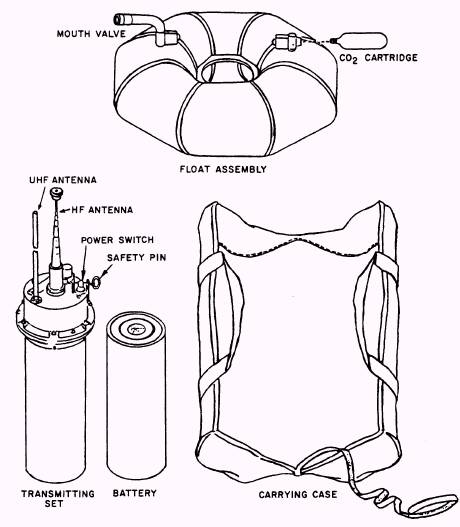
Figure 5-10.-Beacon set, radio, AN/URT-33A (rear view). since the radio is activated when the aircrewman leaves the aircraft.The flexible wire antenna serves as the principal antenna during descent. Upon landing, the flexible antenna is removed by the aircrewman, and a telescopic antenna that is built into the radio is used.The AN/URT-33A radio is battery-operated. The battery is a mercury type with a storage life of 24 months, provided that the storage temperature is 70F. At a storage temperature of 100F, the storage life is only 12 months. For survival equipment applications, such as rigid seat survival kits and life rafts, the service life of the battery assembly is 2 years from the date of manufacture, 225 days from the date placed into service, or 231 days for the SKU-2/A or RSSK-7 seat survival kit. Ensure that the battery service life does not expire prior to the next scheduled inspection of the assembly in which the radio beacon set is installed.AN/PRT-5 TRANSMITTING SET Transmitting Set, Radio AN/PRT-5 (fig. 5-11) is a battery-operated, emergency beacon
Figure 5-11.-Transmitting set, radio, AN/PRT-5, identification of components. 5-11 transmitter that, when properly activated, transmits a tone-modulated radio frequency signal on the emergency guard frequencies of 8.364 MHz and 243.0 MHz simultaneously. The transmitting set includes an inflatable float assembly that keeps the transmitting set afloat at sea, and provides a support platform on land. The entire set is packed in a carrying case for stowing in a life raft. The transmitting set is intended for signaling the location of downed aircraft or airmen. Because it provides signals in both the high frequency (HF) and ultra high frequency (UHF) portions of the spectrum, it can be detected by search aircraft, surface vessels, and coastal-based stations at considerable distances. The battery pack is designed to provide 72 hours of continuous operation at 25C (77F) with at least 250 milliwatts of output from each transmitter at the end of this period. The transmitting set will continue to transmit until the battery pack is completely discharged. Modulation of the transmitter is by internal means only. No provision has been made for voice or code communications, or for receiving signals from search craft. To prepare the radio for use is a simple procedure. 1. Pull the free end of the UHF antenna through the grommet in the float assembly to allow the antenna to stand vertically. 2. Unscrew the top section cap of the telescopic HF antenna, and pull the antenna out to its full length. When fully raised the antenna sections are alternate black and gray with the top section gray. The antenna, when fully extended, is approximately 9 feet high. (See figure 5-12.) 3. Pull out the switch safety pin (fig. 5-11). 4. Turn the POWER toggle switch to ON (fig. 5-11). 5. Place the entire assembly in the water and tow it behind the life raft. 6. When operating on land, be sure the transmitting set is placed on level ground so that the antennas are vertical. Do not stand close to the transmitting set because this can cause changes in the radiation pattern of the transmitted signals. 7. If desired, the safety pin can be replaced to prevent the transmitting set from being turned off accidentally. |
 |