 |
||
|
|
||
| |||||||||||||||
|
|
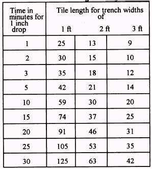
LEACHING FIELDS Leaching fields are an integral component of a septic tank individual sewage disposal system. Leaching field may be referred to as tile fields or absorption trenches. Whichever term is used, the function, testing, construction, and maintenance techniques of this component remain the same. The lines in a leaching fields are built of 4-inch PVC perforated pipe. Many types of perforated pipe are commercially available for use in leaching-field construction. The following conditions are important for the proper functioning of a leaching field: l Groundwater levels well below that of the leaching field . Soil of satisfactory leaching characteristics within a few feet of the surface extending several feet below the leaching pipe l Subsurface drainage away from the field supplies, particularly from shallow wells in the vicinity l Adequate area . Freedom from polluting drinking water Before installing a leaching field in a specified area you must perform a percolation test. This test determines whether the area selected is suitable for subsurface sewage disposal; it also helps you to determine the overall size of the leaching field in relation to trench dimensions and pipe lengths. The test consists of digging a test pit 2 feet square and at least 1 foot in depth. The optimum depth should be at the deepest point that the leaching pipe will be laid. Next dig a hole 1 foot square by 1 foot deep in the test pit. Fill this hole with 7 inches of water for wetting purposes. Allow the water to drop to 6 inches before recording the drop time. Then note the time required for the level to drop 1 inch (from 6 to 5 inches) in depth. You can then determine the length of pipe in the leaching field by using table 10-16. Note that this table is based on the assumption that 4-inch pipe will be used as recommended by the National Standard Plumbing Code. In the construction of a leaching field, the installer takes into consideration the results of the percolation test, type of soil, size of pipe, depth in reference to the ground water level and frost line, and standard requirements of materials Table 10-16.-The Tile Length for Each 100 Gallons of Sewage PerDay 10-37
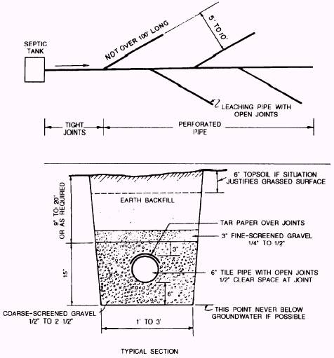
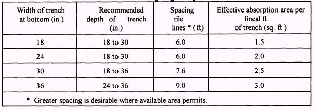
placed in the absorption trench. Figure 10-6 shows a typical layout of a leaching field. The type of soil at the location of the field will dictate the width of the trench. Sand and sandy loam require a width of 1 foot, loam and sand and clay mixture 2 feet, clay with some gravel 3 feet. Note these are minimum trench widths based on the type of soil encountered at the jobsite. Placing the leaching pipe below the frost line to prevent freezing is not necessary. Under no circumstances can you lay leach pipe below the ground water level. When digging the absorption trenches, you must consider the lengths of each lateral and their spacing in relation to each other. Do not make any lateral longer than 100 feet in length. Table 10-17 shows the size and spacing requirements for disposal fields. After the trenches are laid out and dug, filler material must be placed along with the actual pipe. The filler material may be washed gravel, crushed stone, slag, or clean bank-run gravel ranging in size from 1/2 to 2 1/2 inches. Filler material in the trench should not be less than 6 inches deep below the bottom of the pipe. It should be at least 2 inches above the pipe. To prevent backfill soil from filling the voids in the filler material, it is recommended that a 3-inch
Figure 10-6.-Typical layout of a subsurface tile system. 10-38
layer of medium-screened gravel with another layer of fine-screened gravel, untreated paper, or straw of 2 to 3 inches in depth in the trench. Pipe should be laid with a minimum pitch of 2 inches to a maximum pitch of 4 inches per 100 feet, When open joints are used, they must not be spaced more than 1/2 inch apart. Asphalt-treated paper should be used to cover the joint. The open joint allows for free discharge of solids from the line to the trench. The asphalt-treated paper prevents gravel from entering the pipe. The layout of the field requires attention to detail to prevent future maintenance and operation troubles. When the field is laid on sloping ground, the flow must be distributed so each lateral gets a fair portion of the flow. Individual lines should be kid nearly parallel to land contours, Leaching fields are commonly laid out either in a herringbone pattern (fig. 10-6) or with the laterals at right angles to the main distribution pipe. Little or no maintenance is required for leaching fields. Preventive measures, such as excluding all vehicle traffic and not planting trees or shrubs in the field area, should ensure trouble-free operation for many years. When a leaching field becomes inoperable, you must replace it with a new system. Tree or shrub roots are a major factor in leaching-field failure. This requires the replacement of field components and complete root removal. Table 10-17.-Size and Spacing for Disposal Fields
|
|
Privacy Statement - Press Release - Copyright Information. - Contact Us - Support Integrated Publishing |