 |
||
|
|
||
| |||||||||||||||
|
|
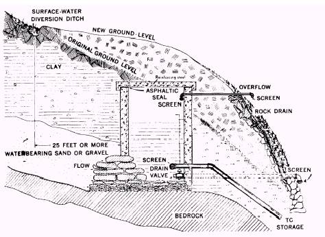
GROUND WATER DEVELOPMENT Moisture is held beneath the surface of the earth in three zones: (1) the zone of soil moisture, where water is temporarily held in pore spaces by capillary action or other soil conditions; (2) the zone of aeration or zone of percolation beneath the soil layer, where both water and air are present in the pore spaces; and (3) the zone of saturation, where all spaces are filled with water. Ground water is the term customarily used for the underground water in the saturated zone. One possible objection to an underground water supply is that the water may be excessively hard. This condition may occur because of the percolation of the water through mineral deposits from which water-hardening constituents are leached or extracted. On the other hand, an underground supply generally has the advantage of requiring less treatment because of the natural removal of impurities as the water passes through various underground soil formations. However, these conditions are general; some mineral deposits do not contribute to hardness, and some underground formations may not be of the type that effectively removes objectionable material. Many times it is advantageous to use shallow ground water sources or percolated waters adjacent to a turbid surface water. Well points are issued in 2-inch diameters and 54-inch lengths. A drive cap is placed over the thread and the well point is driven into the ground with a sledge. Successive sections of pipe, each 5 feet long, are added and driven until the screen is well within the waterbearing media. Several well points may be connected in parallel to supply sufficient water to the raw water pump. In developing drive point sources, it must be remembered that the practical limit of suction lift of the pumps issued with field equipment is 22 to 25 feet at sea level. Suctionlift pumps can be used, therefore, only where the pumping level in the well will be within the limit of suction llift, or 22 to 25 feet below the position of the pump. At 5,000 feet above sea level, the practical limit of suction lift is only 20 feet. It should be noted that since a suction-lift pump must create a partial vacuum in the suction line, it is necessary that the line be absolutely airtight if the pump is to function properly. Springs yielding 20 gallons per minute or more of water can be used as a source of field water supply if properly developed. Springs may be developed by enlarging the outlet of the spring and by damming and conducting water to storage. To reduce possible pollution, springs should be cleared of all debris, undergrowth, top soil, loose rocks, and sand. Water that flows from rocks under the force of gravity and collects in depressions can be collected in boxes or basins of wood, tile, or concrete. The collecting box should be large enough to impound most of the flow. It should be placed below the ground level so only the top is slightly above the surface. The box should be covered tightly to prevent contamination and lessen evaporation. The inlet should be designed to exclude surface drainage and prevent pollution. This requires fencing off the area and providing proper drainage. Figure 9-10 shows a spring inlet protected in this manner. The screen on the overflow pipe prevents the entrance of insects and small animals. Another screen on the intake pipe prevents large suspended particles being ingested by the pump used to distribute the springwater. This prevents mechanical failure or reduces it to a minimum. The flow of water from a spring located on a steep slope of loose earth can be obtained by the following two methods. . Constructing deep, narrow ditches leading from the spring to the point of collection. . Constructing pipeline tunnels from the spring to the collecting points. Pipe of large diameter is more suitable for this purpose. The water from the tunnels can be trapped by constructing a dam at the point of collection. Digging is a more positive and more economical method of developing a spring than blasting. You must proceed with great caution if you use exposives to develop the yield from springs. Blasting in unconsolidated rocks may shift the sand or gravel in such a way as to divert the spring to a different point. The method used for the development of springs as a water source will depend upon the extent and characteristics of the flow. Thermal (hot) springs should not be developed since their waters are likely to be highly mineralized. Regardless of the type of construction, all springs must be covered. Surplus water should be piped from the structure so surface water cannot
Figure 9-10.-Protection of spring from surface contamination. enter the spring during periods of flood. It is not necessary to ventilate spring structures; therefore, all openings should be avoided, except for an inspection manhole fitted with a tight, locked cover. When ground and surface water supplies are inadequate or cannot be used, ground water supplies are developed by constructing wells. Wells are classified into five types, according to their method of construction. These are dug, bored, driven, jetted, and drilled wells. Each type of well has its particular advantages, which may be ease of construction, type of equipment required, storage capacity, ease of penetration into certain types of formations, or ease of safeguarding against pollution. In the event of chemical, biological, and radiological operations, it is important to note that ground water would probably remain essentially uncontaminated by airborne or surface dissemination, in contrast to surface water, which could become severely contaminated. This does not mean that ground water is always pure and safe to drink. It can be naturally contaminated or could, in some cases, become contaminated with CBR agents. Well water should be thoroughly tested before use. The production of ground water involves the method of recovery of water stored in the zone of saturation below the waterline or water table. The ground water table does not always remain at the same elevation, as it is controlled by rainfall, tides, the pumping rate from wells, and so forth. A dug well is a large diameter well, seldom less than 3 feet in diameter, excavated with hand tools, and lined with brick, stone, steel, wood cribbing, or tile. That portion of the lining through the water-bearing formation is porous. This shallow type of well is usually dug from 20 to 40 feet deep, depending upon favorable location for water. Because of the large opening and perimeter to be protected against the incursion of surface drainage, dug wells are easily polluted by surface wash. Bored wells are constructed in soft waterbearing formations that will not cave in while the hole is being bored. They are usually bored with hand or powered earth augers to a depth ranging from 25 to 60 feet without caving in. Jetted wells are suitable in soft, unconsolidated, alluvial deposits. The well consists of an inner tube which is a drilling or jetting tube and an outer tube which is the well-casing. A power-driven pump with suitable hose attachments supplies continuous water pressure during drilling. One type of rig uses a block and tackle or a tripod for controlling the tools and casing. Larger rigs have a mast and hoisting block and use engine power for handling casing, drive weight, and pump. Water is led into the well through a small diameter pipe and forced downward through the drill bit against the bottom of the hole. The stream loosens the material, the finer portion of which is carried upward and out of the hole by the ascending water. During the drilling, the jet or drill is turned slowly to ensure a straight hole. Casing is sunk as fast as drilling proceeds. In softer materials, by using a paddy or expansion drill, a hole may be made somewhat larger than the casing. The casing then may be lowered a considerable distance by its own weight. Ordinarily a drive weight is needed to force it down. As a rule, one size of casing is used for the entire depth of the well. It is difficult to drive a single string of casing beyond 500 to 600 feet by this method. If a well is sunk much deeper, an additional string of smaller size must be used. In fine-textured material the hole often may be jetted to the full depth and the casing inserted afterward. The wall of the hole becomes puddled by the muddy water so it will stand alone. A driven well is constructed by driving a pointed screen, or drive point, and attached pipe directly into a water-bearing formation. The finished well consists of a series of lengths of pipe fitted at the upper end with a pump and the lower end with a sand screen through which the water is admitted. The drive point consists of a perforated pipe with a mild steel point at its lower end to break through pebbles or thin layers of hard material. As the drive point is driven down, succeeding sections are screwed into place. These sections continue until the water-bearing formation is reached. The pump then is attached, and after the well has been developed, it is ready for use. Drive point wells usually range in diameter from 1 1/4 to 2 inches, but larger sizes up to 4 inches also are made. The larger sizes, although of greater weight and more difficult to drive, have the advantage that deep-well pumps can be used when necessary. The smaller sizes, because of their lesser weight and greater portability, are valuable for determining the depth of water-bearing formations and for test yields at shallow depths. The depth of the well is limited by the formations encountered and by the type of pump available. For small wells, the ground water level must be within 25 feet of the surface because suction pumps generally are used. If small self-priming centrifugal pumps are used, the lift must be less than 25 feet. If 2-inch or larger pipes are used, it is possible to lift water from a greater depth by installing a cylinder-type pump near the water level. The following conditions are necessary for successful driven wells. The formation into which the point is being driven must not be too hard and compact. The distance to ground water must not exceed the lift of the pumps available. The waterbearing formations must have moderately high permeability to provide adequate yields in smalldiameter wells. The wells must be developed properly to obtain sufficient water. Chief disadvantages against general use of driven wells are as follows. Construction is laborious and slow when tightly compacted soils are encountered. Driving is destructive to well equipment; points frequently are stripped of mesh; pipe is bent and broken. Couplings frequently are belled by the force of the hammer blows. Belled joints always leak air and either render the well useless or seriously impair the yield of water. Yields are small from any one well point. As many as five points connected in series may be required to operate a power pump to capacity. Successful construction of driven wells depends upon close observation and correct interpretation of events (occurring while driving) by the well driver. Accurate interpretation of such details as the penetration made with each blow, the drop and rebound of the monkey, the sound of the blow, and the resistance of the pipe to rotation enables the experienced well driver to determine the character of the materials being penetrated. An approximation of the geological section of the well can be obtained by recording these observations. Study of the logs for successive wells, coupled with a study of the results obtained from each well, assists in developing trained well drivers with each successive well. Although a well site may have been properly selected, the strata correctly interpreted, and the presence of water accurately judged, wells may fail to yield water merely because they have not been pumped to clear the fine sediment from around the screen. When the presence of water is suspected, a simple test is to pour water into the well. If the screen is in dry sand, the water sinks downward and seeps into the formation, but if the screen is in saturated sand, the level of the added water remains nearly stationary or quickly sinks to a static level. Also the quantity of water that can be poured into the well is an index of the well capacity when pumping; when saturated, the sand yields its contents as freely as it absorbs water. Often the raising or lowering of the pipe a foot or more brings a greater length of the screen into contact with the water-bearing stratum and results in a great increase in yield. There are two methods of drilling wells, one is the hydraulic rotary and the other is the cabletool percussion. Drilled wells tend to be the most complicated and require a lot of equipment. In most cases Equipment Operators will be called upon to place drilled wells. The Utilitiesman may be called upon to install pumps and plumbing when the drilling is complete. Development of this type of well will then proceed in a similar manner as any other type of well. |
|
Privacy Statement - Press Release - Copyright Information. - Contact Us - Support Integrated Publishing |