 |
||
|
|
||
|
Page Title:
Chapter 9 - Water Treatment and Purification |
||
| |||||||||||||||
|
|
CHAPTER 9 WATER TREATMENT AND PURIFICATION As a Utilitiesman, you are responsible for ensuring that an adequate supply of safe water is available for domestic and fire protection uses. In meeting this responsibility you must consider several factors, such as the selection of a water source, ways to develop the water source, contaminants you may encounter, and methods you can use to remove these contaminants. In this chapter, each of these considerations is discussed. WATER SOURCE SELECTION You must consider three factors for a water source: quantity, quality, and reliability. SOURCE QUANTITY Water sources developed for military use are referred to as water points. Water points are classified as follows: 1. Surface water (streams, lakes, and rivers) 2. Groundwater (wells and springs) 3. Seawater 4. Rain, snow, and ice When selecting a water source, you must consider the amount of water available and what the demand is for water. The amount of water that collects in any surface source depends on the amount of precipitation, the size of the drained area, geology, ground surface, evaporation, temperature, topography, and artificial controls. The available water at a source can be estimated by using some simple calculations. To calculate the quantity of water (gallons per minute) flowing in a stream, use the following formula:
An example of this calculation would be a stream having an average depth of 2 feet and a width of 16 feet, and a twig is noted to flow at 13.3 feet per minute. To find the amount of water flowing in the stream, you should work the equation as follows:
To calculate the quantity of water in a lake or pond having little or no runoff, multiply the surface area by the average depth. The answer is cubic feet. Multiply by 7.5 to obtain gallons at the water source. An example of this is a pond with an average depth of 7 feet and a surface area of 2,864 square feet. It is calculated as shown below:
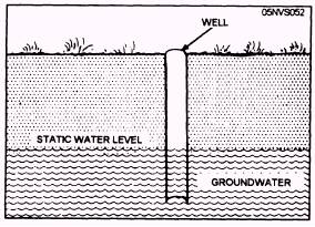
Lakes and ponds are usually located within the water table, and the hydraulics of the water feeding the lake or ponds are similar to that of wells. Therefore, a drawdown test, using a method similar to the one described below for wells, may be used to calculate the quantity of water. To perform the test, you should draw down the static water level to 1 or 2 feet and then record the recovery time. Also, devise a method to discharge the water being pumped so it does not return to the source during the test. To calculate the quantity of water that can be supplied from newly constructed or existing wells, you must make a drawdown test. To perform this test properly, you must understand the hydraulics of a well. Before being pumped, the level of water in a well is the same as the level of the water table in the water-bearing formation in which the well is completed. This is called the static level in the well and in the foundation. (fig. 9-1). The depth from the ground surface to the static water level should be measured and this distance used to describe its position. Thus if the water in the well
Figure 9-1.-Static water level before pumping. is 25 feet below ground, the static water level is said to be 25 feet for this well. Elevation of the static water level above mean sea level can also be used to describe its position. When a well is pumped, the water level drops. After several hours of pumping at a constant rate, it stabilizes itself in a lower position. This is called the pumping level or dynamic water level for this rate of pumping (fig. 9-2). The distance the water is lowered by pumping is called the drawdown. It is the difference between the static level and the pumping level. The drawdown in the well, resulting from pumping, lowers the water pressure in the well, but the surrounding water-bearing formation retains its original pressure. In response to this difference in pressure, water flows out of the pores of the formation into the well. The water-bearing formation does not furnish its water all at once to the well being pumped. The flow of water into the well is held back by the frictional resistance offered by the formation to the flow of water through its pores. The resistance varies in each formation and is developed in direct proportion to the rate of movement or velocity of the water in the formation. The rate of flow, resulting from a given pressure difference, depends on the fictional resistance to flow developed in the formation. The term used to describe this characteristic of a porous material is permeability. For a particular type of well, the yield of the well for any given drawdown is
Figure 9-2.-Pumping level. directly proportional to the permeability of the formation. This property of the formation varies through wide ranges, the value for a coarse sand stratum being several hundred times that of a fine sand stratum of the same thickness. It increases with the coarseness of the sand and decreases with the compactness of the material. It increases where the sand grains are more nearly uniform in size. It decreases when fine sand and silt fill the voids between larger particles. The permeability of a rock formation, like limestone, varies with the number and sizes of the fractures, crevices, and solution channels. The measurements that should be made in testing wells include the volume of water pumped per minute or per hour, the depth to the static water level before pumping is started, the depth to the pumping level at one or more constant rates of pumpage, the recovery of the water level after pumping is stopped, and the length of time the well is pumped at each rate during the testing procedure. The testing described in this chapter is essentially the measurement of the hydraulic characteristics of a particular well. The pump and power unit used for testing a well should be capable of continuous operation at a constant and variable rate of pumpage for a period of over 24 hours. It is important that the equipment be in good condition for an accurate test, since it is undesirable to have a forced shutdown during the test. The test pump should be large enough to test to the expected capacity of the well, even though this may be far beyond the amount of water required and may exceed the capacity of the permanent well pump. Pumping by airlift maybe a practical method, provided that meters are not used for measuring the flow. The test should run at least 24 hours. Longer tests, up to several weeks' duration, may be desirable to verify adequacy of the formation. To determine the safe yield of the well, the pump should be operated at a rate that will cause only about 50 percent of the maximum possible drawdown. The drawdown should not exceed a point 5 feet above the topmost screen slot. For example, a 125-foot well has a static water level of 25 feet and a pumping level of 75 feet or a 50-foot drawdown. The satisfactory pumping level is 50 feet or 50 percent of the maximum drawdown. Therefore, a safe well capacity is established and maintained for that condition regardless of the yield. The safe pumping yield is the withdrawal rate that will not cause a lowering of the water table, and should cause no more than 50 percent of maximum drawdown. A chart, similar to the one shown in figure 9-3, should be
Figure 9-3.-Well chart. 9-3
included in the test report. The complete test report will include the following: 1. Initial static water level 2. Pumping rates, at least every hour 3. Drawdown data, at least every hour 4. Rate of recovery The simplest way to measure the water pumped is to catch it in a steel drum or other tank of known volume. The time required to fill the tank is determined as accurately as possible. The rate of pumpage in gallons per minute is then calculated. For reasonable accuracy, the tank should be large enough to hold the water pumped during a period of at least 2 minutes. This limitation makes the method practical only for relatively small wells, since large tanks will not usually be available. Water meters offer a definite advantage in measuring the water being pumped. The amount of water pumped may be recorded from the meter at desired intervals. The total discharge may be recorded for any individual phase of the drawdown test. The most accurate way to measure depth to the static level and to the pumping level in a well is with a chalked tape. A steel tape with a weight to make it hang straight is chalked at the lower end with blue carpenter's chalk and lowered into the well until 1 or 2 feet of the tape is submerged. The proper length to lower the tape may have to be determined by experiment. The wetted length of the tape shows up very clearly on the chalked portion of the tape. This length is subtracted from the total length lowered below the reference point; this gives the depth to water. The drawdown observed during a well test is the difference in feet between the Table 9-1.-Daily Water Requirements in Temperate Zone
pumping level and the static water level before pumping was started. The specific capacity of the well is the yield or discharge in gallons per minute divided by the drawdown in feet. Water needs should be estimated, using per capita requirements and other controlling demands as factors in arriving at the estimate. Other controlling demands may be the water requirements for such items as fire protection, industrial uses, lawn sprinkling, construction, leakage, and water delivered to other activities, and vehicles. Table 9-1 shows the per capita daily water requirements for different situations, and the daily average requirements for vehicles. Table 9-2 indicates the requirements that may be needed for construction equipment. Compare the yield of the source with the needs of the activity. |
|
Privacy Statement - Press Release - Copyright Information. - Contact Us - Support Integrated Publishing |