 |
||
|
|
||
| |||||||||||||||
|
|
SPRINKLER SYSTEM DETECTION AND INDICATING DEVICES AND FITTINGS Sprinkler systems have many different controlling devices and fittings. These can be classified as detecting or initiating devices or fittings. Their function is to detect system operation and to initiate system operation or alarm systems connected to the sprinkler system. This section discusses these devices and fittings to aid you in installing and troubleshooting sprinkler systems and understanding the interface between the mechanical and electrical functions of these devices. Water-Flow Actuated Detectors Sprinkler water-flow detectors are generally pressure-actuated or vane-actuated. Pressure switches are used on both wet and dry pipe systems. Vane switches are widely used on wet pipe sprinkler systems. They cannot be used on dry pipe systems because the initial rush of water into the pipe could damage the vane and mechanism. Dry pipe system alarms tend to be slow-acting because it takes time to lose sufficient air through a fused sprinkler to trip the system. Various methods are used to speed up dry pipe systems as discussed earlier. Wet pipe system alarms have a different problem. Fluctuating water pressure frequently causes flow into a sprinkler system, equalizing the sprinkler system pressure with the supply pressure. Such surges of water or of pressure cause false water-flow alarms if some method of slowing
Figure 8-19.-Open sprinklers.
Figure 8-20.-Water spray nozzles. down the switch response to the surge is not used. Various retarding techniques are used, some associated with the sprinkler piping and some with the water-flow detector. The pressure increase type of water-flow detector (fig. 8-21) comes in numerous styles. It is found in wet or dry pipe sprinkler systems. The usual arrangement for switch actuation includes a sealed accordionlike bellows that is assembled to a spring and linkage. The spring-tension setting controls the pressure at which the flow detector is actuated. It can be field adjustable and/or factory set to the desired pressure that activates the electrical switch. If this pressure switch is to be used on a wet pipe system, it is usually mounted at the top of a retarding chamber. This reduces the speed of pressure buildup at the switch. Other styles of this switch incorporate a pneumatic retarding mechanism within the detector housing. The retard time is adjustable to a maximum of 90 seconds. Usual settings are in the range of 20 to 70 seconds. The retard switch is connected to the alarm port of a wet sprinkler system alarm check
Figure 8-21.-Pressure increase type of water-flow detector. valve. It is usually set for a pressure range of 8 to 15 psi. Pressure drop detectors can be used in wet pipe sprinkler systems equipped with a check valve (alarm check or swing check) that holds excess pressure on the system side of the check valve. These detectors are frequently used where a water surge or hammer causes false alarms with other types of water-flow detectors. The construction of pressure drop detectors is similar to the pressure increase detectors. The switch for a pressure drop detector is arranged to actuate on a drop in pressure. There is no retarding mechanism or chamber. A typical switch of this type would be adjusted for a normal operating pressure in the range of 50 to 130 psi. The alarm pressure would be adjustable between 10 to 20 psi below normal pressure. A vane type of water-flow detector (fig. 8-22) is used only in wet pipe sprinkler systems. The detector is assembled at the pipe by drilling a hole in the wall of the sprinkler pipe, inserting the vane into the pipe, then clamping the detector on with U-bolts. When the sprinkler system is actuated by fire, the water flowing through the pipe causes the
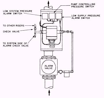
Figure 8-22.-Vane type of water-flow detector. vane to move. A mechanical linkage connects the vane to an adjustable retarding device, usually a pneumatic dashpot. The retarding device actuates the alarm switch or switches and/or signal transmitter. The retarding device setting is usually in the range of 30 to 45 seconds. A maximum setting may be as high as 90 seconds if necessary. The pressure pump/pressure drop type of water-flow detector is used in large sprinkler systems and in those systems with inadequate water pressure to reliably operate one of the other types of water-flow detectors. These detectors are also known as fixed-pressure, water-flow detectors, with pump (fig. 8-23). This detector has a pump, pump motor, and control unit. It is arranged for strap-mounting to the sprinkler system riser. The device provides a water-flow alarm signal, a low system water pressure supervisory signal, and excess pressure in the system to prevent surges in the supply pressure from opening the alarm check valve and causing operation of the water motor gong or other alarm indicators. A typical detector of this type is adjusted to maintain the system pressure at 25 to 50 psi above supply pressure. A slow leak at the alarm check valve or anywhere in the system will cause the system pressure to drop slowly. When pressure decreases to 2 psi below the preset value, a pressure switch closes, causing the pump to start pumping water from the supply side to the system side of the alarm check valve at a rate of about 1 gallon per minute (gpm). If the total system leaks less than 1 gpm, the pressure switch opens and stops the pump when the preset pressure is reached. However, if the system leaks are greater than 1 gpm, system pressure will continue to drop even with the pump running. If system pressure decreases to 4 psi below the preset value, a trouble pressure switch opens to indicate that there is a leak greater than 1 gpm. If the water pressure continues to drop to 6 psi below the preset value, an alarm pressure switch closes, signaling a waterflow alarm. Some water-flow detectors of this type have an additional switch that disconnects pump power when the supply water pressure drops below 14 psi. This prevents pump burnup in case of total supply shutdown or a break in the supply line.
Figure 8-23.-Fixed pressure water-flow detector with pump. The electronic pressure drop detector is often used in sprinkler systems that must maintain a high excess system pressure over supply pressure that would delay actuation of a vane type of water-flow detector. It is normally mounted to the riser pipe with a flexible hose connection to the system side of the check valve. This device requires a pressure drop of 5 to 20 ounces per square inch continuing over a period of at least 3 seconds to signal an alarm. A pressure drop at a slower rate or of a shorter duration causes no alarm. A slow pressure drop to 15 psi or less causes a trouble signal indicating a system leak and low supply pressure. Pressure increases do not cause an alarm, but an over pressure condition (200psi) causes a trouble signal. Trouble signals will also be initiated when the detector's cover is opened, supply voltage is outside normal ranges, and an internal circuit fails, interfering with detector function. |
|
Privacy Statement - Press Release - Copyright Information. - Contact Us - Support Integrated Publishing |