 |
||
|
|
||
|
Page Title:
Tubing or Wiring to fire detection system |
||
| |||||||||||||||
|
|
TUBING OR WIRING TO FIRE DETECTION SYSTEM
Figure 8-12.-Combined system header arrangement. TYPES OF SPRINKLERS Sprinklers are nozzles placed at intervals along the piping network to distribute a uniform pattern of water on the area being protected. To attain maximum efficiency, the stream of water must be broken into droplets. A deflector (part of the frame of the sprinkler) breaks up the water. You, as a UT, will generally install sprinklers to meet the specifications and plans of a project. When you require more information on proper locating of sprinklers, refer to the National Fire Protection Association Code Book Number 13 (NPFA #13), entitled Installation of Sprinkler Systems. Automatic sprinklers are designed for specific applications based on orifice size, deflector design, frame finish, and temperature rating. Sprinklers have orifices ranging in size from 1/4-inch to 1/2-inch diameter graduated by 1/16-inch increments. There is also one 17/32-inch size orifice. Deflectors give different patterns of water distribution and allow the sprinkler to be placed in various locations such as upright, pendent, or sidewall (fig. 8-13). Next, sprinkler frames may
Figure 8-13.-Sprinkler deflector styles.
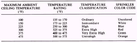
be plated for appearance or they maybe coated for protection from an adverse environment. For example, sprinklers that will be used in corrosive atmospheres are either lead- or wax-coated. Finally, automatic sprinklers are normally held closed by heat-sensitive elements that press down on a cap over the sprinkler orifice and are anchored by the frame of the sprinkler. The heatsensitive elements melt and release at different temperatures depending on application. Sprinklers are color coded to identify the temperature range rating of the fusible element (table 8-1). Color coding is not required for plated sprinklers, ceiling sprinklers, or similar decorative types. There are basically four types of release mechanisms for automatic sprinklers. They are the fusible link, frangible bulb, frangible pellet, and bimetallic element.
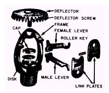
Figure 8-14.-Fusible link automatic sprinkler. The fusible link sprinkler (fig. 8-14) is kept closed by a two-piece link held together by a solder with a predetermined melting point. When the solder melts, the levers pull the two-piece link apart and fly away from the sprinkler. Pressure in the piping network pushes the cap from the orifice of the sprinkler to discharge water. The frangible bulb sprinkler (fig. 8-15) has a small bulb made of glass between the orifice cap and the sprinkler frame. The bulb is partially filled with a liquid. Air fills the remaining space. Heat from a fire will cause the liquid to expand against the air causing the glass bulb to shatter and opening the sprinkler for water discharge.
Figure 8-15.-Frangible bulb automatic sprinkler. Table 8-1.-Sprinkler Temperature Ratings
the supervised system should record in inches of water rather than pounds per square inch. The second system is the unsupervised preaction system. It has no means of continuous monitoring. |
|
Privacy Statement - Press Release - Copyright Information. - Contact Us - Support Integrated Publishing |