 |
||
|
|
||
| |||||||||||||||
|
|
SINGLE-PHASE HERMETIC MOTORS Basically, there are four types of single-phase motors used in hermetic assemblies: the splitphase; the capacitor-start, induction-run; the capacitor-start, capacitor-run; and the permanent split-phase. Each motor is discussed in this section. SPLIT-PHASE The split-phase motor is used generally on condensing units of 1/10-, 1/6-, and 1/4-horsepower
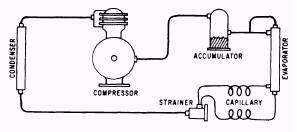
Figure 14-24.-Accumulator location.
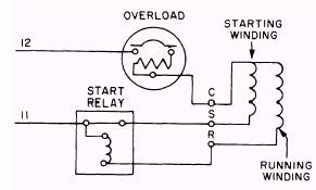
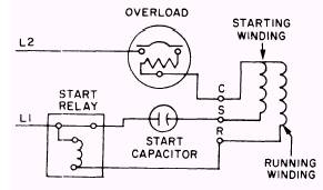
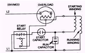
Figure 14-25.-Schematic wiring diagram of a split-phase motor circuit. capillary tube systems. It has a low starting torque and contains both a starting winding and a running winding. A disconnect device is required for the starting winding when the motor reaches sufficient speed to operate on the running winding. Figure 14-25 is a schematic wiring diagram of a split-phase motor circuit. CAPACITOR-START, INDUCTION-RUN This motor is similar to the split-phase type except that a starting capacitor is connected in series with the starting winding to provide higher starting torque. Figure 14-26 is a schematic diagram illustrating this type of motor. A device is also required to disconnect the starting winding when the motor reaches rated speed. This motor is commonly used on commercial systems up to three-fourths horsepower. CAPACITOR-START, CAPACITOR-RUN Two capacitors are used with the capacitorstart, capacitor-run motor: a starting capacitor and a running capacitor. The capacitors are in parallel with each other and in series with the starting winding. Figure 14-27 is a schematic diagram illustrating this type of motor circuit. The two capacitors turn the motor power surges into two-phase power when the motor is started. At approximately two-thirds rated speed, the starting capacitor part of the circuit is disconnected by a start relay device. Only the running capacitor remains in the circuit. This type of motor has a
Figure 14-26.-Schematic wiring diagram of a capacitor-start induction-run motor.
Figure 14-27.-Schematic wiring diagram of a capacitor-start capacitor-run motor.
high starting torque and is used with hermetic systems up to 5 horsepower. |
|
Privacy Statement - Press Release - Copyright Information. - Contact Us - Support Integrated Publishing |