 |
||
|
|
||
|
Page Title:
Chapter 13 - Duct and Ventilation Systems |
||
| |||||||||||||||
|
|
CHAPTER 13 DUCT AND VENTILATION SYSTEMS As a Utilitiesman, you can expect to become involved in the installation of duct and/or ventilation systems designed to provide conditioned air or to remove less desirable air from a given space or facility. When sheet metal is to be fabricated into system components, the Steelworker provides the expertise. When duct board is used, fabrication and installation may be tasked to the Utilitiesman exclusively. This chapter provides some key knowledge to aid you in the identification of types of duct and ventilation systems, their installation, and factors you must be aware of in determining the sizes required to meet specified building requirements. Keep in mind that the term air conditioned refers to air that has been cooled, heated, dehumidified or humidified, or any combination of these. DUCT SYSTEMS To deliver air to the conditioned space, you need air carriers. These carriers are called ducts. They are made of sheet metal or some structural material that does not bum (noncombustible). Duct systems are also classified as high-pressure or high-velocity ductwork and low-pressure or low-velocity ductwork. The term high-pressure or high-velocity ductwork includes ductwork systems and plenums from the fan discharge to the final high-velocity mixing boxes, or other final pressure-reducing devices or any air supply system served by a fan operating with a static pressure range of 3 inches to 7 inches of water column (WC). High-velocity or high-pressure systems with fan static pressures of 3 inches WC or greater are defined as high pressure. Usually the static pressure is limited to a maximum of 7 inches WC, and duct velocities are limited to 4,000 feet per minute (fpm). Systems requiring pressures more than 7 inches WC are normally unwarranted and could result in very high operating costs. Systems with velocities more than 4,000 fpm peforms satisfactorily when all duct fittings are carefully designed and installed. However, velocity pressure losses are excessive and velocities more than 4,000 fpm are not recommended. A high-velocity double-duct system begins with a high-pressure fan of class II or III design any conveys air through sound-treated high-velocity ductwork connected to sound and pressure-attenuating mixing units. Connections to the outlets of the reduction units are treated as low velocity. Smaller sized ductwork, using higher velocities, permits conveyance of air to areas limited by construction and reduces floor-to-floor height. Round ductwork generally provides the greatest strength, tightness, and economy. However, oval and rectangular ducts can be used when large risers are involved. A necessary component of the high-pressure system is the mixing box or unit. Its function is to blend air at two different temperatures for proper delivery to the rooms. This requires special pressure-reducing air valves at both hot and cold inlets, mixing baffles to prevent stratification of air, and sound attenuation treatment to absorb noise generated by the air valves.
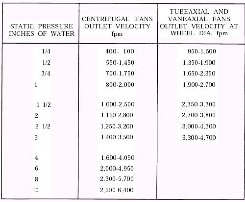
Table 13-1.-Outlet Velocities for Optimum Performance of Fans
The term low-pressure or low-velocity ductwork applies to systems with fan static pressures less than 3 inches WC. Generally, duct velocities are less than 2,000 feet per minute. The choice between the use of low versus highvelocity systems requires architectural, mechanical, and structural considerations. Installation cost, temperature control, and operating cost should also be studied. Low-velocity double duct systems are many years old. It was not until after World War II that their use became extensive. Space for the installation of the double ducts is a main consideration for this system and must be provided during initial planning. Difficulties in providing for this space in modern structures with low floor-to-floor heights and flush ceilings, together with the need for developing a compact distribution system for existing buildings, has brought about the development of high-velocity double duct systems. High velocity saves ceiling space and duct shaft space, but requires greater attention in the selection of fans and equipment with regard to sound levels. Also, higher duct velocities require increased fan static pressures; therefore, increased operating costs. On the other hand, high-velocity systems are easy to balance and control and have much greater flexibility for partition changes and so forth. Generally, high-velocity systems are applicable to large multistory buildings; primarily because the advantage of saving in duct shafts and floor-to-floor heights is more substantial. Small two- and three-story buildings are normally low velocity; however, both systems should be analyzed for each building. Table 13-1 shows outlet velocities for the range of optimum performance of typical ventilation fans. Ducts are made of many types of materials. Pressure in the ducts is small, so materials with a great deal of strength are not needed. Originally, hot air ducts were thin, tinned sheet steel. Later, galvanized sheet steel, aluminum sheet, and
TABLE 13-2.-Materials for Ductwork
finally. insulated ducts made from materials, such as asbestos and fiberboard, were developed. Passageways, formed by studs or joists, are sometimes used for return air when a fire hazard does not exist. Ducts made of asbestos are no longer legal. If discovered, asbestos in any form must be removed and disposed of according to the laws and regulations discussed in chapter 16 of this manual. The material used for the construction of ductwork depends on the application of the duct. Use table 13-2 as a guide in the selection of duct material. The thickness of the material depends primarily on the pressure developed within the duct, the length of the individual sections, and the cross-sectional area of the duct. The developed length of a section for a particular gauge can be increased by installing angle bracing around the duct. It is beyond the scope of this manual to include the technical details necessary for the selection of proper metal thickness and section length for different pressures and for different crosssectional areas of duct material. However when repairs are made, the same thickness of metal that was originally included in the system must be installed. Where the original ductwork was destroyed by pressure, repairs may include increasing metal thickness or adding of angle bracing. Ducts are either round or rectangular in cross section. Although rectangular ducts usually have the advantage of saving room space and being easier to install in walls, round ducts provide less resistance to air flow and should be used whenever possible. Additionally, round ducts require less material to construct; thus, by using round ducts, you can save both money and material during installation. Initially, an air-handling duct is usually sized for round ducts. Then, if rectangular ducts are wanted or required, duct sizes can be selected to provide flow rates equivalent to those of the round ducts originally selected. Table 13-3 is a ready reference to determine the size of a rectangular duct that equals the carrying capacity of a predetermined round duct. To use this chart, convert a rectangular duct with sides of 17 inches by 16 inches, respectively. First, come down the left-hand column until you reach 17 inches; then trace the line horizontally across the columns until you reach the column headed by 16 inches. At the center of these intersecting lines is 18.0 inches. This is the round duct size equivalent. In the second example, following the same procedure, it is clearly shown that a 22-inch by 17-inch rectangular duct has a 21-inch round duct equivalent. |
|
Privacy Statement - Press Release - Copyright Information. - Contact Us - Support Integrated Publishing |