 |
||
|
|
||
| |||||||||||||||
|
|
Tube Inspection When inspecting the exterior of boiler tubes, look for signs of warping, bulging, sagging, cracking, pitting, scaling, acid corrosion, and other damage. All tube sheets should be inspected for signs of leakage, especially the superheater tube sheet. Inspection of boilers sometimes shows an unexpected condition in which adjacent boiler tubes are warped in such a way that they touch each other. When this condition exists, the tubes are said to be married. Tube marriages can result either from overheating of the tubes or from stresses developed in the tubes during installation. For the latter reason, newly erected boilers and boilers that have been retubed should always be inspected for tube alignment after the initial period of steaming. When inspection reveals one or more tube marriages, the decision as to whether or not the married tubes should be renewed should be based on the following considerations: 1. If the tube marriage occurs in screen tubes 1 1/2 inches or larger, or if the furnace side wall or rear wall tubes are bowed, tube replacement is usually required. 2. If 1-inch or 1 1/4-inch tubes in the main bank of generating tubes are married, replacement is usually not required if the tube joints are tight under hydrostatic test. 3. Inspect the external surfaces of the tubes. If they show blistering or other signs of overheating, the tubes should be renewed. 4. Inspect the watersides. Where tube marriages exists, a poor waterside condition may indicate hard scale or oil within the affected tubes. If hard scale or oil does exist, the married tubes should be replaced, and all appropriate steps should be taken to remove the scale or oil from the rest of the boiler. If the condition of the tubes is uncertain, or if a large number of tube marriages have occurred, remove one or more sample tubes, split them, and examine them carefully. 5. Tube marriages may cause gas laning, and gas laning, in turn, may cause local overheating of the inner casing, the bottom part of the economizer, and other parts. Inspect the boiler carefully for signs of local overheating that might have been caused by gas laning resulting from the tube marriages. If the local overheating from this cause is found, renew the married tubes. 6. On single-furnace boilers, a lane more than 1 1/2 inches wide may allow overheating of the superheater and of the superheater supports. If a large lane (1 1/2 tubes wide or wider) exists near the superheater outlet header end of the boiler, the married tubes that caused such a large lane should be renewed. To identify the cause of the tube failure by visual inspection, you will need to know something about the various ways in which tubes rupture, warp, blister, and otherwise show damage. Tube failures must be reported, and they must be reported in standard terminology. The following sections of this chapter deal with the inspection techniques required for determining the causes of tube failure and with the various ways in which boiler tube damage is classified and identified. The inspection techniques required for determining the cause of tube failure must naturally vary according to the nature of the problem. For example, a rupture in a fire row tube can usually be described adequately on the basis of simple visual observation, but the cause of damage to a tube that is deep in the tube bank cannot usually be determined without removing the intervening tubes. When a blistered tube suggests a waterside deposit, the nature and extent of the deposit can be determined only by removing and splitting the tube so that the waterside can be examined. Relatively simple equipment is required for the field inspection of damaged or fouled pressure parts. Equipment for this purpose should include the following: (1) devices for measuring tube diameters, depth of pits, and thickness of deposits; (2) instruments for separating deposits and corrosion products-a sharp knife, a chisel, a steel scribe, or a vise to crack deposits loose from the tube samples; (3) an approved type of portable light; (4) a supply of clean bottles for collecting samples of deposits; and (5) a mirror for viewing relatively inaccessible places. Many of these items of equipment can be improvised if necessary. For example, a simple gauge for measuring the depth of waterside pits may be made by pushing a straight pin or a paper clip through a 3-by 5-inch card so that the point of the pin or clip projects beyond the card, at right angles to the card. Such an improvised depth gauge is shown in figure 12-8. A section of string can be wrapped around a deformed tube and then laid along a ruler to obtain a measure of tube enlargement or tube thinning. Of course, special tools such as calipers, depth gauges, and scale thickness indicators give more accurate results and should be used if they are available; but the improvised tools, if used with care, can also give good results. The classification of boiler tube damage is considered here under four major classifications: (1) fireside cavities and scars, (2) waterside cavities and scars, (3) tube deformities and fractures, and (4) tube deposits. FIRESIDE CAVITIES AND SCARS on the tube firesides often indicate the reasons for tube failure. The term circumferential groove is used to describe the metal loss that occurs in bands or stripes around the circumference of a tube. Fireside grooving of this type often occurs at the header ends of horizontal tubes such as superheater tubes. The most common cause of this damage is leakage from tube seats higher in the tube bank. The grooving occurs as the water runs
Figure 12-8.-Improvised depth gauge.
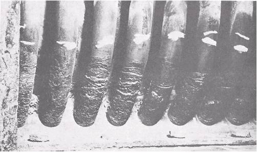
Figure 12-9.-General fireside circumferential grooving. down the header and onto the tube ends, or as it drips directly onto the tubes. This kind damage is greater on the top of the tube than on the underside, but the groove may extend the entire circumference. Fireside circumferential grooving may also occur on vertical generating tubes as a result of thin, damp deposits of soot on horizontal drums or headers. In fact, this kind of grooving can occur in any part of the boiler where leakage provides a sufficient supply of water. Large quantities of water trapped between the water drum and the boiler casing-as, for example, from a serious economizer leak-can produce general fireside grooving around the bottom of the rear generating tubes. An example of this general fireside circumferential grooving is shown in figure 12-9. CRATERS are deep, irregular, straight-walled cavities in the tube metal. WATER TRACKS are closely related to craters; the tracks consist of wandering, straight-walled, canyon-like cavities in the tube metal. Both cratering and water track-ing occur almost exclusively at the header ends of water wall tubes and division wall tubes that are surrounded by refractory; they are caused by water becoming trapped between the tube metal and the surrounding refractory. Water washing of boiler firesides, without proper drying out, is a frequent cause of cratering and water tracking; of however, any leak higher in the boiler can also cause this type of damage. The size of the leak around and the angle of the tube upon which the water leaks determine, to a large extent, whether the resulting damage will be circumferential grooving, cratering, or water tracking. Both cratering and water tracking are shown in figure 12-10. GENERAL FIRESIDE THINNING consists of a uniform loss of metal over a relatively large area on the outside of the tube. Soot corrosion is by far the most common cause of general fireside thinning. The parts that are particularly subject to this kind of damage are superheater
Figure 12-10.-Fireside catering and water tracking.
tube ends between the headers and the seal plates, water drum ends of generating tubes, and return bends in economizer tubes. General fireside thinning of a generating tube is shown in figure 12-11. A rather unusual type of general fireside metal loss sometimes results from the combination of extremely high tube temperatures and the burn-ing of fuel oil that contains vanadium compounds. The vanadium compounds carried in the flame can cause rapid oxidation of metal at high temperatures. This type of damage is unusual in water-cooled parts of the boiler, since critical temperatures are not usually attained. Figure 12-12 shows a stainless steel superheater tube that has suffered this type of general thinning as a result of fuel ash damage. |
|
Privacy Statement - Press Release - Copyright Information. - Contact Us - Support Integrated Publishing |