 |
||
|
|
||
| |||||||||||||||
|
|
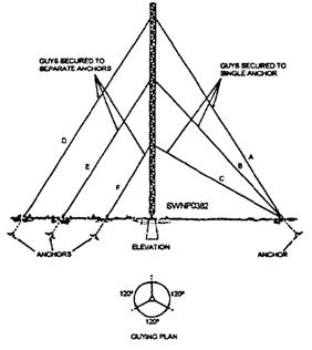
GUYING Temporary guying of steel towers is always necessary where more than one tower section is erected. Under no circumstances should the tower be advanced more than two sections without guying. Permanent guys are to be installed before the temporary ones are removed. Temporary Guying Several materials, including stranded wire, wire rope, and fiber line, are all acceptable for temporary guying. New manila line is the most suitable because of its strength and ease of handling. The size of the guyed material required is determined by the height and weight of the structure to be guyed and by weather conditions at the installation site. Secure the temporary guys to the permanent guy anchors to temporary type anchors or to any nearby structure that provides the required supporting strength. Leave the temporary guys in place until the structure is permanent y guyed and plumbed. Permanent Guying Antenna structures are permanently guyed with steel cables or fiber glass sections to pre-positioned anchors according to the installation plan. Figure 8-37 shows two methods of guying triangular steel towers. Guys A, B, and C are secured to a single anchor, while guys D, E, and F are secured to individual anchors. Both arrangements are satisfactory. However, the anchor that terminates guys A, B, and C must be capable of withstanding much greater stresses than the individual guy anchor arrangement. Triangular tower guys are arranged so
Figure 8-37.-Tower-guying arrangements. that three guys are spaced 120 degrees apart at each level of guying (fig. 8-36). Square towers require four guys spaced 90 degrees apart at each level of guying (fig. 8-37). Square towers require four guys spaced 90 degrees apart at each guying level. The following general elevation requirements apply to guy attachments for towers: SINGLE-GUY LAYER The cable attachments are placed in position at approximately two thirds of the tower height. TWO-GUY LAYERS. For towers with two-guy layers, cable attachments are placed in positions at approximately 30 and 80 percent of the tower height. THREE-GUY LAYERS. For towers with three-guy layers, cable attachments are placed in positions at approximately 25,55, and 85 percent of the tower height. Tower Guy Tension Setting guy tension and plumbing a tower are done at the same time and only when wind forces are light. Guy tension adjustment and tower plumbing are done as follows: INITIAL TENSION. All of the guys should be adjusted gradually to the approximate tensions specified in the antenna installation details. If tensions are not specified, guy tension should be adjusted to 10 percent of the breaking strength of the strand of the
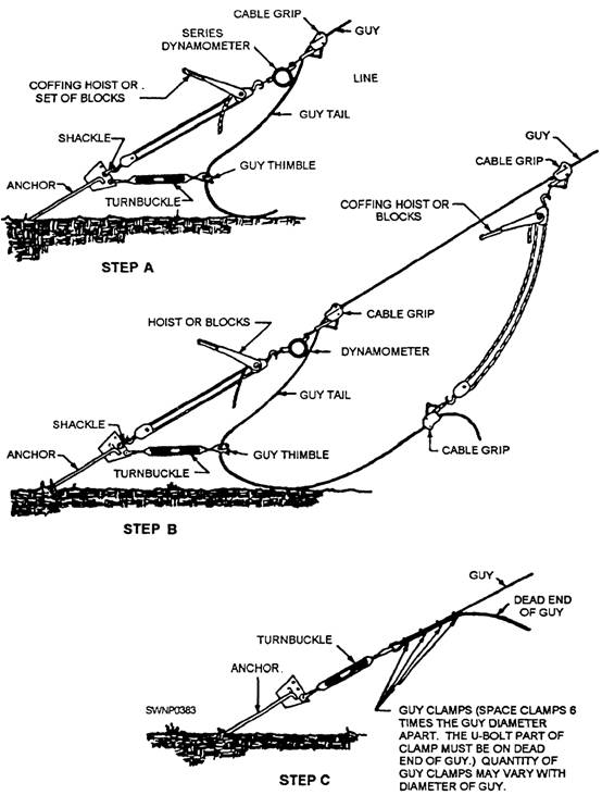
Figure 8-38.-Final tensioning of guys. guy. The tension on all of the guys is adjusted after the tower is in a stable, vertical position. FINAL GUY TENSION. In one procedure used for final tensioning of tower guys, the final tension is measured with a dynamometer, as shown in figure 8-38. Carpenter stoppers or cable grips of the proper skin, designed for the lay of the wire, must be selected for use in the tensioning operation. Any cable grip assembly that grips the wire by biting into the cable
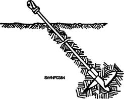
Figure 8-39-Typical screw anchor. with gripping teeth could penetrate and damage the protective coating of guy cables and should not be used In step A of figure 8-38, the coffing hoist is shown in series with a dynamometer to measure the tension. A turnbuckle is shown in position to receive the guy tail. In step B, an additional cable grip and hoist or tackle are attached above the cable grip shown instep A. The lower end of this tackle is provided with a second cable grip that is' attached to the guy tail previously threaded through the turnbuckle. The second coffing hoist is operated until sufficient tension is applied to cause the reading on the series dynamometer to fall off. Step C shows the guy in final position secured in place with clamps. With the tower properly plumbed to a vertical position, only one guy at a given level need be tested with the dynamometer. On some installations, other procedures for tensioning guys may be necessary because of the type of guys and hardware supplied with the antenna. For example, preformed wire helical guy grips are sometimes used for attaching guy wires to the adjusting turnbuckles. In such cases, the techniques used for the guy assembly, the connection of the guy wire to the anchor, and the tension adjustments must be determined for the detailed installation plan or the appropriate antenna technical manual. Guy Anchors Antenna design and installation plans specify the anchor type, the location, and the hole depth required. Anchor shafts, or rods, must project above the grade sufficiently to keep all of the connecting guy wire attachments free of vegetation and standing water. Shafts and connecting attachments should be thoroughly cleaned and then coated with a petroleum preservative to retard the effects of weather. SCREW ANCHOR. The screw anchor shown in figure 8-39 may be used for temporary guying and for anchoring guys for lightweight towers. This anchor is installed by screwing it into the ground in line with the direction the guy will take. EXPANSION ANCHOR. The expansion anchor shown in figure 8-40 is suitable for practically all guying applications where the soil is firm. This anchor is placed with its expanding plates in the closed position in an auger-drilled inclined hole, not less than 3 feet deep. The plates are expanded into the firm, undisturbed sides of the hole by striking the expanding bar at point B with a hammer and thereby forcing the sliding collar downward the distance D shown in figure 8-40. The anchor installation is completed by backfilling the hole with thoroughly tamped backfill. CONCRETE ANCHORS. Poured in-place concrete anchors are normally used for high stress applications and where multiple guys are attached to a single anchorage.
Figure 8-40.-Expansion anchor. |
|
Privacy Statement - Press Release - Copyright Information. - Contact Us - Support Integrated Publishing |