 |
||
|
|
||
| |||||||||||||||
|
|
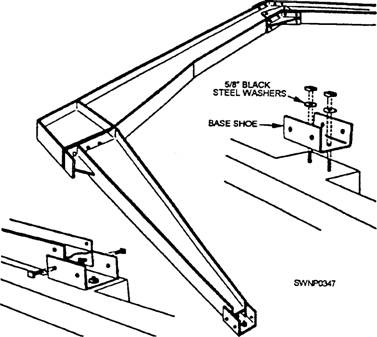
ERECTION PROCEDURES With all pre-erection work completed, inspected, and passed by Quality Control, as well as your inventory completed, you are ready to start erecting the P.E.B. This phase of our discussion will introduce you to the basic erection procedures. The reason for these instructions is to give you a general guide to follow. Keep in mind that the drawings provided by the manufacturer must be followed in all cases, even where the they might differ from information in this training manual. The manufacturer's standard practice is to always pack an erection manual and a set of drawings in the small parts box (Box 1) shipped with each building. Bolting Rigid Frames Before bolting up the rigid-frame assembly, clean all the dirt and debris from the top of the foundation, Then lay out and bolt the base shoes firmly to the concrete, using the 5/8-inch black steel washers between the shoes and the nuts. Lay out an assembled column and roof beam at each pair of base shoes (fig. 8-4), using one 3/4-inch by 1 1/2-inch bolt on each side of each base shoe to act as pivots in raising the frame. Use driftpins, if necessary, to line up the holes. Frame Erection A gin pole (chapter 6) can be used to raise the end frame of the building. To prevent distortion of the
Figure 8-3.-StructuraI members of a pre-engineered building.
Figure 8-4.-Frame assembly. frame when it is being raised, attach a bridle securely to each side of the frame below the splice connection and also to the ridge on the roof beam. Drop a driftpin in the flame, as shown in figure 8-5, to prevent the bridle from slipping up. Set up the gin pole with a block at the top. If a gin pole is not available, take three 2 by 6's, 20 feet long, from the longest shipping crate and nail them together. Attach a tag line to the name, as shown in figure 8-5. Now, pull the end frame into the vertical position, using a crew of four or five people on the erection line. A tag person should have something to take a couple
Figure 8-5.-Frame erection. of turns around, such as the bumper of a truck. Then, if the frame should go beyond the vertical, the tag person would be able to keep it from falling. To get the frame started from the ground, it should be lifted by several people and propped up as high as practical. Bolt an cave strut to each column, as shown in figure 8-5. The cave struts allow the frame to be propped at every stage of the lifting. After the frame is in a vertical position, install guy lines and props to it so it cannot move. Now, raise the second frame in the same way, and hold it vertically in place by installing purlins, girts, and brace rods. A crane or other suitable type of power equipment can be used to hoist the frames into place where such equipment is available. When power equipment is used, the suggested procedure to comply with is as follows: 1. Raise the columns and bolt them to the base shoes and then brace them in plain. 2. Install all sidewall girts to keep the columns as rigid as possible. 3. Bolt the roof beams together and install the gable posts and end-wall header. 4. Secure the guy lines, and tag lines to the roof beams, as shown in-figure 8-6. Attach a wire rope sling at approximately the center of each roof beam. 5. Hoist the roof beams into position on top of the columns and bolt them in place. 6. When the second rigid-frame section is secured in position, install all of the roof purlins, the gable angles, and the louver angles. Attach the gable clips to the purlins before raising into position. 7. Install the brace rods and align the first bay. THE FIRST BAY MUST BE ALIGNED BEFORE ERECTING ADDITIONAL BAYS. Brace Rods Brace rods must be installed in the first bay erected (fig. 8-7). These rods are of paramount importance since the y hold the frames in an upright position. THEY SHOULD NEVER BE OMITTED. The diagonal brace rods are attached to the frames in the roof and sidewall through the slotted holes provided. Use a half-round brace rod washer and a flat steel washer under the nuts at each end of the rods.
Figure 8-6.-Using power equipment. With the rods installed, plumb each frame column with the carpenter's spirit level. Check the distance diagonally from the upper comer of one frame to the lower comer of the adjacent frame. When this distance is the same for each rod, the columns will be plumb. After the sidewall rods are installed, install the roof rods. The length of the roof rods can be adjusted by tightening or loosening the turnbuckle. When the two diagonal measurements are the same, the end bay will be square. After the two frames have been plumbed and braced square with the diagonal rods (and the purlins, the girts, and the eave struts have been installed), the guy lines or props can be removed and the remaining frames of the building can be erected. To raise the next frame, attach blocks to the last frame raised. 2 Do not omit the diagonal brace rods that are required in the last bay of the building. 2. Be sure and bolt the girts, the purlins, and the cave struts to the inside holes of the end frames. 2 Install the cave struts, the girts, and the purlins in each bay as soon as a frame is erected. Z Exercise care to see that the diagonal brace rods are taut and do not project beyond the flanges of the end frame to interfere with end-wall sheeting.
Figure 8-7.-Braoe rods. Sag Rods Sag rods are used to hold the purlins and the girts in a straight line. First, install the sag rods that connect the two purlins at the ridge of the building. Each rod must be attached from the' top hole of one purlin through the bottom hole of the adjacent purlin. Use two nuts at each end of the sag rods-one on each side of each purlin. Adjust the nuts on these rods, so the purlins are held straight and rigid. Next, install the sag rods between the purlins below the ridge with the rod attached from the top hole of the upper purlin through the bottom hole of the lower purlin. Use two nuts on each end-one on each side of each purlin. Follow the same procedure with the sidewall sag rods. Remember that the roof purlins should show a straight line from end to end of the building. Do NOT tighten the sag rods so much that the purlins are twisted out of shape. Brace Angles and Base Angles After two or more bays have been erected, part of the erection crew can be assigned to install the diagonal brace angles. To install the brace angles, lay the notched portion against the frame flange and bend it into position (fig. 8-8). Diagonal brace angles are needed to support the inner flange of the frame. Be sure to install them so that they are taut. While some members of the crew are installing brace angles, other members can be installing base angles. When assigned this duty, first, sweep off the top of the concrete foundation, so the base angles will set down evenly. Bolt the base angles in place with a flat steel washer under the nut. Leave the nuts loose to permit later adjustments after the wall sheeting has been applied. End-Wall Framing/Doors/Windows Refer to the manufacturers' specifications for proper assembly and installation procedures for end-wall framing, doors (both sliding and roll-up), and
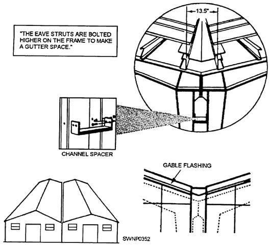
Figure 8-8.-Diagonal brace angles windows, as these procedures will vary with available building options. Sheeting Sheeting, both sidewall and roof, must always be started at the end of the building toward which the prevailing winds blow. This action will ensure that the exterior joint in the side laps is away from the blowing of the prevailing winds. When installing roof sheeting, always use a generous amount of mastic on the upper side of all roof sheets just before moving them to the roof. Turn the sheet over and put a bead of mastic on the lip of one side of the corrugation and along one end (near the end but never more than one 1 inch from the end). Be sure to apply a horizontal bead of mastic between all sheets in the end laps, BELOW THE LAP HOLES. The roof sheets must be dry when mastic is applied. Mastic is extremely important, and care should be exercised whenever applying it to ensure a watertight seal. Apply generous beads, especially at the comers of the sheets. Finally, the ridge cap will be installed ensuring proper watershed. As previous] y stated, the information in this manual is general information common to pre-engineered buildings. Building Insulation The pre-engineered building can be insulated by any of several methods. A blanket type of insulation, in 2-foot-wide strips, to match the width of the roof and wall sheets can be installed between the sheets and structural at the same time the sheeting is installed. Or, a hardboard insulation can be applied directly to the inside surface of the structural, attaching it by helix nails or by sheet-metal screws in holes prepared by drilling of the structural. Or, a wood framing can be prepared, attached to the structural, and a hardboard insulation is nailed to the wood. Buildings Set Side by Side "In Multiples" Pre-engineered buildings can easily be set upside by side to increase the working area under one roof. When this is done, the adjacent rigid frames should be bolted back to back with a channel spacer at each girt location (fig. 8-9). The cave struts are moved up the roof beam to the second set of 11/16-inch-diameter holes to provide a gutter. This arrangement provides a space between cave struts of 13 1/2 inches. A field-fabricated gutter can be installed. Flat, unpainted galvanized steel of 24-to 26-gauge material should be used for the gutter. A depth of 6 1/4 inches is desirable with the downspouts located as required. Gutter ends should be lapped at least 6 inches and should be braze-welded for watertightness. Note that wall sheets can be used to form a gutter if the outside corrugations are flattened and all of the end laps are braze-welded. Roof sheets must be cut shorter where they overhang the gutter. The corrugations can be closed with the continuous rubber closure with mastic applied to the top and bottom surfaces of the closure. An alternate method is to flatten the corrugations at the gutter and seal them with a glass fabric stripping set in plastic.
Figure 8-9.-Buildings side by side. |
|
Privacy Statement - Press Release - Copyright Information. - Contact Us - Support Integrated Publishing |