 |
||
|
|
||
| |||||||||||||||
|
|
FLEXIBLE CONNECTIONS Most duct systems are connected to either a heating or a cooling system. These systems are general] y electric motor driven to move air through the duct system. Therefore, all inlet and outlet duct connections to all fans or other equipment that may
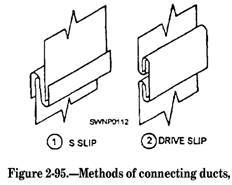
Figure 2-93.-Easement around an obstruction in ducts. create vibration should be made with heavy canvas, as shown in figure 2-94. The most common method of making connections between duct sections and fittings is the method of
Figure 2-94.-Flexible duct connection. combining two S slips and two drive slips (fig. 2-95). S slips are first placed on two opposite edges of one of the sections or fittings to be joined. These S slips are applied to the widest dimension of the duct (fig. 2-96). The second section or fitting is then inserted into the slips, and the two sections are held together by inserting drive slips along the opposite sides [fig. 2-97). After the drive slips are driven home, they are locked in place by bending the ends of the drive slip over the comer of the S slips to close the comer and leek the drive slips in place (fig. 2-98), completing the joint shown in figure 2-99. HANGING DUCT FROM PURLINS OR BEAMS Most of the ductwork Steelworkers install, modify, or repair are in pre-engineered buildings or repairs to more permanent type of ducting in buildings, such as barracks and base housing. The most common installation method is hanging the duct from purlins or beams in the hidden area of a
Figure 2-96.-Placing S slips for S-and-drive connection.
Figure 2-97.-Inserting drive slips.
Figure 2-98.-Bending drive slips to complete the Joint. roof or below a ceiling. Figure 2-100 shows one such system when the duct is running parallel to the structural member. These systems require that angle be installed between the beams so that the hanger straps can be installed on both sides of the duct. Normally, 2-inch by 2-inch by 1/8-inch angle is
Figure 2-99.-Completed S-and-drive connection.
Figure 2-100.-Duct running parallel to purlins or beams. sufficient. However, if the duct is of a very large size, a larger angle may be required. The straps that are used as hangers may be fabricated from 1/8-inch plate. In a normal installation, a 1 inch by US-inch strap will suffice. All straps must be connected to the ductwork with sheet-metal screws. On all government work, it is required that the screws be placed 1 1/4 inches from all edges, as illustrated in the figure which shows that the duct system hanging from angle rails and that all angles be either bolted or tack-welded to purlins or beams. Strap hangers may be hung directly on purlins or beams when the duct is running transverse] y or across the purlins or beams, as shown in figure 2-101. However, the strap hangers must be twisted to turn 90
Figure 2-101.-Strap hangers from purlins. degrees onto the flange of the beam or purlin. Again, the standard 7 feet 10 inches maximum span required between hangers applies. Also, the hanger screws standard will apply. The hanger span may be shortened to fit the job requirements. For heavier or larger systems, an installation similar to that shown in figure 2-102 maybe required. This system is hung entirely on angle rails and the straps are fabricated into one-piece units. This system is by far the neatest looking and is normally used when the duct system is exposed. Installing a duct system under a built-up steel roof (fig. 2-103) is accomplished by hanging the duct system with all-thread bolts and 2-inch by 2-inch by 1/8-inch angles. The all-thread bolt protrudes through the steel decking and is bolted from the top with a large washer and bolt, which extends down alongside the duct into the 2-inch by 2-inch angles which is also bolted from under the angle. This system allows for adjustment of height. Also notice that the all-the ad bolt extends into the top flat of the apex of the steel roof decking. This is required because connecting the all-thread bolt to the bottom valley of the steel deck will reduce the structural strength of the decking and may also cause water leaks. |
|
Privacy Statement - Press Release - Copyright Information. - Contact Us - Support Integrated Publishing |