 |
||
|
|
||
| |||||||||||||||
|
|
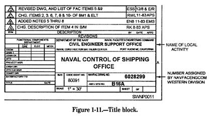
ORDER OF PROJECT DRAWINGS Project drawings for buildings and structures are arranged in the following order: 1. TITLE SHEET AND INDEX-Contain specific project title and an index of drawings. (Used only for projects containing 60 or more drawings.) 2. SITE or PLOT PLANS-Contain either site or plot plans or both, as well as civil and utility plans. For small projects, this sheet should include an index of the drawings. 3. LANDSCAPE AND IRRIGATION (if applicable). 4. ARCHITECTURAL (including interior design as applicable). 5. STRUCTURAL. 6. MECHANICAL (heating, ventilation, and air conditioning). 7. PLUMBING. 8. ELECTRICAL. 9. FIRE PROTECTION. Title Blocks The title block identifies each sheet in a set of drawings. (See fig. 1-11.) Generally, the title block is located at the bottom right comer of the drawing regardless of the size of the drawing (except for vertical title block). For further information on the layout of title blocks, refer to the Engineering Aid 3. The information provided in the title block is important information that a Steelworker MUST understand. The information includes the following: Architect's name Architect's seal Drawing title Date prepared Revisions Designed by Checked by Drawing numbers Name of local activity Code ID number (80091 NAVFAC) Letter designation Size of drawing Scale of drawing ABFC drawing number (if applicable) Approved by There are many variations to title blocks. Depending on the preparing activity (NAVFAC, NCR, NMCB, etc.), all title blocks should contain the same information listed above. Drawing Revisions A Revision block contains a list of revisions made to a drawing. The Revision block is located in the upper right-hand corner. The Revision block can include a separate "PREPARED BY" column to indicate the organization, such as an architectural engineering firm, that prepared the revision. Like title blocks, revision blocks can vary in format with each command. Graphic Scales Graphic scales are located in the lower right-hand comer of each drawing sheet, with the words Graphic Scales directly over them. The correct graphic scales must be shown prominent y on each drawing because, as drawings are reduced in size, the reductions are often NOT to scaled proportions. Remember, scaling a drawing should be done as a "last resort." Drawing Notes NOTES are brief, clear, and explicit statements regarding material use and finish and construction methods. Notes in a construction drawing are classified as specific and general. SPECIFIC notes are used either to reflect dimensional information on the drawing or to be explanatory. As a means of saving space, many of the terms used in this type of note are often expressed as abbreviations. GENERAL notes refer to all of the notes on the drawing not accompanied by a leader and an arrowhead. As used in this book, general notes for a set of drawings covering one particular type of work are placed on the first sheet of the set. They should be
placed a minimum of 3 inches below the space provided for the revision block when the conventional horizontal title block is used. When the vertical title block is used, you can place the general notes on the right side of the drawing. General notes for architectural and structural drawings can include, when applicable, roof, floor, wind, seismic, and other loads, allowable soil pressure or pile-bearing capacity, and allowable unit stresses of all the construction materials used in the design. Notes for civil, mechanical, electrical, sanitary, plumbing, and similar drawings of a set can include, when applicable, references for vertical and horizontal control (including soundings) and basic specific design data. General notes can also refer to all of the notes grouped according to materials of construction in a tabular form, called a SCHEDULE. Schedules for items, like doors, windows, rooms, and footings, are somewhat more detailed. Their formats will be presented later in this chapter. |
|
Privacy Statement - Press Release - Copyright Information. - Contact Us - Support Integrated Publishing |