 |
||
|
|
||
| |||||||||||||||
|
|
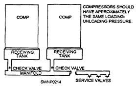
A compressor is a machine for compressing air from an initial intake pressure to a higher exhaust pressure through reduction in volume. A compressor consists of a driving unit, a compressor unit, and accessory equipment. The driving unit provides power to operate the compressor and may be a gasoline or diesel engine. Compressors are governed by a pressure control system adjusted to compress air to a maximum pressure of 100 psi. Compressed Air System A compressed air system consists of one or more compressors, each with the necessary power source, control of regulation, intake air filter, aftercooler, air receiver, and connecting piping, together with a distribution system to carry the air to points of use. The object of installing a compressed air system is to provide sufficient air at the work area at pressures adequate for efficient operation of pneumatic tools being used. Many construction projects require more cubic feet of air per minute than any one compressor will produce. Terrain conditions often create problems of distance from the compressor to the operating tool. Since the air line hose issued with the compressor causes considerable line loss at distances farther than 200 feet, a system has been devised for efficient
Figure 12-27.-A drill bit sharpening attachment mounted on a conventional bench grinder. transmission of compressed air over longer distances. This system is called air manifolding (fig. 12-28). An air manifold is a pipe having a large diameter used to transport compressed air from one or more compressors over a distance without detrimental friction line loss. In construction work, air manifolds are usually constructed of 6-inch diameter pipe. A pipe of this size can carry 1,200 cubic feet per minute (cfm) of air (output from two 600 cfm air compressors) at 100 psi with less than .035 pound pressure loss per 100 linear feet. One or more compressors pump air into the manifold and eventually "pressurize" it at 100 psi; then air may be used at any point along the manifold by installing outlet valves and connecting air lines and pneumatic tools. Compressor Operation and Maintenance The following paragraphs will give generaI instructions on operating and maintaining air compressor units. A compressor must be located on a reasonably level area. Most compressors permit a 15-degree lengthwise and a 15-degree sidewise limit on out-of-level operation. The limits are placed on the engine, not the actual compressor. When the unit is to be operated out-of-level, it is important to do the following: (1) keep the engine crankcase oil level near the high-level mark (with the unit level) and (2) have the compressor oil gauge show nearly full (with the unit on the level). An instruction plate, similar to the one shown in figure 12-29, is attached to all compressors. Notice that this plate refers you to the manufacturer's engine and compressor manuals for detailed instructions. STARTING THE UNIT.- Take the following steps when starting the engine during mild weather:
Figure 12-28.-Methods of manifolding compressors.
Figure 12-29.-Operating Instruction plate. 1. Open the service valves about one quarter-not wide open. NOTE: The reason for starting with the service valves partly open is that they aid in quicker warm-up of the compressor oil. 2. Position the low-pressure, engine-oil-system safety knob to ON (fig. 12-30). 3. Turn the ignition switch to the START position. Immediately after the engine starts, release the ignition switch. If the engine fails to fire within 30 seconds, release the ignition switch and allow the starting motor to cool off for a few moments before trying the starter again. 4. With the engine running, check the engine oil pressure gauge. If no pressure is indicated, turn the engine off. When the oil pressure goes above 22 psi, continue to operate the engine and check the low-pressure engine oil switch. The knob on this switch should be in the RUN position. NOTE: The engine oil pressure gauge indicates erratically until the engine oil warms up. 5. Open the side curtains on both sides of the engine enclosure and leave them open. The flow of air through the oil cooler and engine radiator will be impeded if the side curtains are closed while the engine is running. 6. After the engine has run about 3 minutes, check the engine coolant temperature gauge. The gauge should indicate less than 210F. If the gauge is showing more than 210F, SHUT OFF THE ENGINE.
Figure 12-30.-Instrument panel. 7. After 5 minutes of operation, close the service valve and attach the hose or service line of the tool or device to be operated. 8. Open the service valves fully and start the work. After start-up, the unit automatically provides compressed air at the discharge service valves. Only periodic checking of the gauges on the instrument panel is then required. 9. When the engine is started during the day, after the first daily start-up, the above warm-up steps maybe eliminated, STOPPING THE UNIT.- When stopping the unit at the end of the day, you should take the following steps: 1. Close the service valves and permit the engine to run at idle for 5 minutes. This will allow the engine coolant temperature to level off and the entire unit to cool down. 2. Turn the ignition switch to the OFF position. COLD-WEATHER START-UP.- The following steps should be completed during cold-weather Start-up: 1. Start the engine using the heater switch and priming pump according to the engine manual. 2. Warm the engine until the engine coolant temperature reaches 120F. Leaving the side curtains closed for a few minutes helps the engine to warm up. 3. Turn the ignition switch to OFF. 4. When the engine has stopped, start the engine again with the service valves partly open. Be sure the side curtains are open. 5. When the compressor has run for several minutes and the gauges indicate normal operating conditions, connect up the tools and go to work. LUBRICATING THE UNIT.- The lubrication chart in the operator's manual for the particular make and model of compressor you are operating will show you where the unit should be lubricated, how often to lubricate, and what lubricant to use. The frequency will vary depending upon operating conditions and usage. Operating under abnormal conditions requires more frequent service. CAUTION Before servicing the compressor air system or compressor oil system, open the service valves to the atmosphere to relieve all pressure in the systems. SERVICING THE AIR CLEANER.- A two-stage, dry type of air cleaner, installed inside the engine enclosure at the right rear, falters the intake air (fig. 12-31). Air is drawn into a first-stage element that causes nearly all the dust in the air to drop into a bin. Air then enters the second-stage element, a paper cartridge, where more dust is trapped and collected. The dustbin should be removed by hand and emptied daily. Some models have a self-emptying dustbin that is piped into an aspirator in the exhaust pipeline, just beyond the muffler. When the aspirator is used, no alterations are allowed to be made to the engine muffler or exhaust pipe. A service indicator is mounted on the side of the air cleaner housing. As the paper cartridge clogs with dust, a red indicator flag gradually rises in the window. When the cartridge is completely loaded, the window will show all red, and the flag will be locked in place. It is time to replace the paper cartridge, Discard the old cartridge and reset the red flag so that the window shows clear. Cleaning used paper cartridges is not recommended.
Figure 12-31.-Air cleaner. |
|
Privacy Statement - Press Release - Copyright Information. - Contact Us - Support Integrated Publishing |