 |
||
|
|
||
| |||||||||||||||
|
|
DESTRUCTIVE TESTING In destructive testing, sample portions of the welded structures are required. These samples are subjected to loads until they actually fail. The failed pieces are then studied and compared to known standards to determine the quality of the weld. The most common types of destructive testing are known as free bend, guided bend, nick-break, impact, fillet welded joint, etching, and tensile testing. The primary disadvantage of destructive testing is that an actual section of a weldment must be destroyed to evaluate the weld. This type of testing is usually used in the certification process of the welder. Some of the testing requires elaborate equipment that is not available for use in the field. Three tests that may be performed in the field without elaborate equipment are the free-bend test, the guided-bend test, and the nick-break test. Free-Bend Test The FREE-BEND TEST is designed to measure the ductility of the weld deposit and the heat-affected area adjacent to the weld. Also it is used to determine the percentage of elongation of the weld metal. Ductility, you should recall, is that property of a metal that allows it to be drawn out or hammered thin. The first step in preparing a welded specimen for the free-bend test is to machine the welded reinforcement crown flush with the surface of the test plate. When the weld area of a test plate is machined, as is the case of the guided-bend as well as in the free-bend test, perform the machining operation in the opposite direction that the weld was deposited. The next step in the free-bend testis to scribe two lines on the face of the filler deposit. Locate these lines
Figure 7-61.-Free-bend test
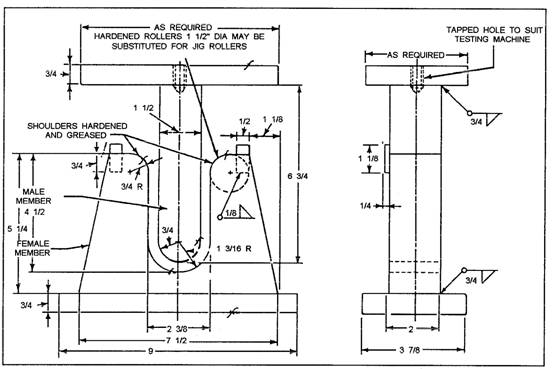
Figure 7-62.-Guided-bend test jig. 1/16 inch from each edge of the weld metal, as shown in figure 7-61, view B. Measure the distance, in inches, between the lines to the nearest 0.01 inch and let the resulting measurement equal (x). Then bend the ends of the test specimen until each leg forms an angle of 30 degrees to the original centerline. With the scribed lines on the outside and the piece placed so all the bending occurs in the weld, bend the
Figure 7-63.-Guided-bend test specimens. test piece by using a hydraulic press or similar machine. When the proper precautions are taken, a blacksmith's forging press or hammer can be used to complete the bending operation. If a crack more than 1/16 inch develops during the test, stop the bending because the weld has failed; otherwise, bend the specimen flat. After completing the test, measure the distance between the scribed lines and call that measurement (y). The percentage of elongation is then determined by the formula: X x 100 = % elongation Requirements for a satisfactory test area minimum elongation of 15 percent and no cracks greater than 1/16 inch on the face of the weld. Guided-Bend Test You use the GUIDED-BEND TEST to determine the quality of weld metal at the face and root of a welded joint. This test is made in a specially designed jig. An example of one type of jig is shown in figure 7-62. The test specimen is placed across the supports of the die. A plunger, operated from above by hydraulic pressure, forces the specimen into the die. To fulfill the requirements of this test, you must bend the specimen 180 degrees-the capacity of the jig. No cracks should appear on the surface greater than 1/8 inch. The facebend tests are made in this jig with the face of the weld in tension (outside), as shown in figure 7-63. The rootbend tests are made with the root of the weld in tension (outside), as shown in figure 7-63. Figure 7-64 shows a machine used for making the guided-bend test. It is used in many welding schools and
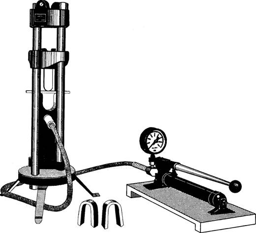
Figure 7-64.-Testing machine for making guided-bend tests.
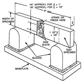
Figure 7-65.-Nick-break test of a butt weld testing laboratories for the daily testing of specimens. Simple in construction and easy to use, it works by hydraulic pressure and can apply a direct load up to 40,000 pounds, and even more on small specimens. When you make the test, position the specimen in the machine as previously indicated and start pumping the actuator. Keep your eye on the large gauge and watch the load increase. You will know the actual load under which the test piece bends by the position of an auxiliary hand that is carried along by the gauge pointer. The hand remains at the point of maximum load after the pointer returns to zero. Nick-Break Test The NICK-BREAK TEST is useful for determining the internal quality of the weld metal. This test reveals various internal defects (if present), such as slag inclusions, gas pockets, lack of fusion, and oxidized or burned metal. To accomplish the nick-break test for checking a butt weld, you must first flame-cut the test specimens from a sample weld (fig. 7-65). Make a saw cut at each edge through the center of the weld. The depth of cut should be about 1/4 inch. Next, place the saw-nicked specimen on two steel supports, as shown in figure 7-65. Using a heave hammer, break the specimen by striking it in the zone where you made the saw cuts. The weld metal exposed in the break should be completely fused, free from slag inclusions, and contain no gas pockets greater than 1/16 inch across their greatest dimension. There should not be more than six pores or gas pockets per square inch of exposed broken surface of the weld. Impact Test You use the IMPACT TEST to check the ability of a weld to absorb energy under impact without
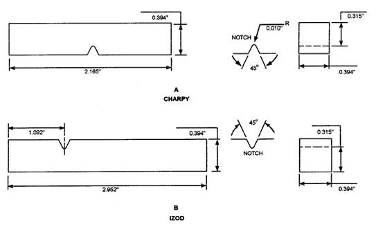
Figure 7-66.-Test pieces for impact testing.
Figure 7-67.-Performing impact test. fracturing. This is a dynamic test in which a test specimen is broken by a single blow, and the energy used in breaking the piece is measured in foot-pounds. This test compares the toughness of the weld metal with the base metal. It is useful in finding if any of the mechanical properties of the base metal were destroyed by the welding process. The two kinds of specimens used for impact testing are known as Charpy and Izod (fig. 7-66). Both test pieces are broken in an impact testing machine. The only difference is in the manner that they are anchored. The Charpy piece is supported horizontally between two anvils and the pendulum strikes opposite the notch, as shown in figure 7-67, view A. The Izod piece is supported as a vertical cantilever beam and is struck on the free end projecting over the holding vise (fig. 7-67, view B). Fillet-Welded Joint Test You use the FILLET-WELDED JOINT TEST to check the soundness of a fillet weld. Soundness refers to the degree of freedom a weld has from defects found by visual inspection of any exposed welding surface. These defects include penetrations, gas pockets, and inclusions. Prepare the test specimen, as shown in figure 7-68. Now apply force at Point A
Figure 7-68.-Test plate for fillet weld test.
Figure 7-69.-Rupturing fillet weld test plate. (fig. 7-69) until a break occurs in the joint. This force may be applied by hydraulics or hammer blows. In addition to checking the fractured weld for soundness, now is a good time to etch the weld to check for cracks. Etching Test The ETCHING TEST is used to determine the soundness of a weld and also make visible the boundary between the base metal and the weld metal. To accomplish the test, you must cut a test piece from the welded joint so it shows a complete transverse section of the weld. You can make the cut by either sawing or flame cutting. File the face of the cut and then polish it with grade 00 abrasive cloth. Now place the test piece in the etching solution. The etching solutions generally used are hydrochloric acid, ammonium persulfate, iodine and potassium iodide, or nitric acid. Each solution highlights different defects and areas of the weld. The hydrochloric acid dissolves slag inclusions and enlarges gas pockets, while nitric acid is used to show the refined zone as well as the metal zone. Tensile Strength Test The term TENSILE STRENGTH may be defined as the resistance to longitudinal stress or pull and is measured in pounds per square inch of cross section. Testing for tensile strength involves placing a weld sample in a tensile testing machine and pulling on the test sample until it breaks.
Figure 7-70.-Standard tensile test specimen. The essential features of a tensile testing machine are the parts that pull the test specimen and the devices that measure the resistance of the test specimen. Another instrument, known as an extensometer or strain gauge, is also used to measure the strain in the test piece. Some equipment comes with a device that records and plots the stress-strain curve for a permanent record. The tensile test is classified as a destructive test because the test specimen must be loaded or stressed until it fails. Because of the design of the test machine, weld samples must be machined to specific dimensions. This explains why the test is made on a standard specimen, rather than on the part itself. It is important that the test specimen represents the part. Not only must the specimen be given the same heat treatment as the part but it also must be heat-treated at the same time. There are many standard types of tensile test specimens, and figure 7-70 shows one standard type of specimen commonly used. The standard test piece is an accurately machined specimen. Overall length is not a critical item, but the diameter and gauge length are. The 0.505-inch-diameter (0.2 square inch area) cross section of the reduced portion provides an easy factor to manipulate arithmetically. The 2-inch gauge length is the distance between strain-measuring points. This is the portion of the specimen where you attach the extensometer. In addition, you can use the gauge length to determine percent elongation. The tensile test amounts to applying a smooth, steadily increasing load (or pull) on a test specimen and measuring the resistance of the specimen until it breaks. Even if recording equipment is not available, the testis not difficult to perform. During the test, you observe the behavior of the specimen and record the extensometer and gauge readings at regular intervals. After the specimen breaks and the fracturing load is recorded, you measure the specimen with calipers to determine the percent of elongation and the percent reduction in area. In addition, you should plot a stress-strain curve. From the data obtained, you can determine tensile strength, yield point, elastic limit, modulus of elasticity, and other properties of the material. |
|
Privacy Statement - Press Release - Copyright Information. - Contact Us - Support Integrated Publishing |