 |
||
|
|
||
| |||||||||||||||
|
|
NONDESTRUCTIVE TESTING Nondestructive testing is a method of testing that does not destroy or impair the usefulness of a welded item. These tests disclose all of the common internal and surface defects that can occur when improper welding procedures are used. A large choice of testing devices is available and most of them are easier to use than the destructive methods, especially when working on large and expensive items. Visual Inspection Visual inspection is usually done automatically by the welder as he completes his welds. This is strictly a subjective type of inspection and usually there are no definite or rigid limits of acceptability. The welder may use templates for weld bead contour checks. Visual inspections are basically a comparison of finished welds with an accepted standard. This test is effective only when the visual qualities of a weld are the most important. Magnetic Particle Inspection Magnetic particle inspection is most effective for the detection of surface or near surface flaws in welds.
Figure 7-58.-Circular magnetization (prod method).
Figure 7-59.-Longitudinal magnetization (coil method). It is used in metals or alloys in which you can induce magnetism. While the test piece is magnetized, a liquid containing finely ground iron powder is applied. As long as the magnetic field is not disturbed, the iron particles will form a regular pattern on the surface of the test piece. When the magnetic field is interrupted by a crack or some other defect in the metal, the pattern of the suspended ground metal also is interrupted. The particles of metal cluster around the defect, making it easy to locate. You can magnetize the test piece by either having an electric current pass through it, as shown in figure 7-58, or by having an electric current pass through a coil of wire that surrounds the test piece, as shown in figure 7-59. When an electric current flows in a straight line from one contact point to the other, magnetic lines of force are in a circular direction, as shown in figure 7-58. When the current flow is through a coil around the test piece, as shown in figure 7-59, the magnetic lines of force are longitudinal through the test piece. When a defect is to show up as a disturbance in the pattern of the iron particles, the direction of the magnetic field must be at right angles to the major axis of the defect. A magnetic field having the necessary direction is established when the current flow is parallel to the major axis of the defect. Since the orientation of the defect is unknown, different current directions must be used during the test. As shown in figure 7-58, circular magnetism is induced in the test piece so you can inspect the piece for lengthwise cracks, while longitudinal magnetism, as shown in figure 7-59, is induced so you can inspect the piece for transverse cracks. In general, magnetic particle inspection is satisfactory for detecting surface cracks and subsurface cracks that are not more than 1/4 inch below the surface. The type of magnetic particle inspection unit commonly used in the Navy is a portable low-voltage unit having a maximum magnetizing output of 1,000 amperes, either alternating or direct current. It is ready to operate when plugged into the voltage supply specified by the manufacturer. The unit consists of a magnetizing current source, controls, metering, three 10-foot lengths of flexible cable, and a prod kit. The prod kit includes an insulated prod grip fitted with an ON-OFF relay or current control switch, a pair of heavy copper contact prods, and two 5-foot lengths of flexible cable. Cable fittings are designed so that either end of the cable can be connected to the unit, to the prods, or to any other cable. The three outlets on the front of the unit make changing from alternating to direct current or vice versa very easy. The outlets are labeled as follows: left is ac, the center is COMMON, and the right is dc. One cable will always be plugged into the COMMON outlet, while the other cable is plugged into either the ac or do outlet, depending upon what type of current the test requires. For most work, alternating current magnetization effectively locates fatigue cracks and similar defects extending through to the surface. When you require a more sensitive inspection to detect defects below the surface, use direct current. You can use the unit with alternating or direct current in either of two ways: (1) with prods attached to the flexible cable and used as contacts for the current to pass into and out of a portion of the test piece, setting up circular magnetization in the area between the prods contact points, as shown in figure 7-58; or (2) with the flexible cable wrapped around the work to form a coil that induces longitudinal magnetism in the part of the workpiece that is surrounded by the coiled cable (fig. 7-59)0 Although you can use either of these two methods, the prod method is probably the easier to apply. Inmost instances, it effectively serves to detect surface defects. With the prods, however, only a small area of the test piece can be magnetized at any one time. This magnetized area is limited to the distance between prod contact points and a few inches on each side of the current path. To check the entire surface, you must test each adjacent area by changing the location of the prod contact points. Each area of the test piece must be inspected twiceonce with the current passing through the metal in one direction and then with the current passing through the metal in a direction at right angles to the direction of the first test. One of the advantages of the prod method is that the current can be easily passed through the metal in any desired direction. Thus, when a given area is suspect, magnetic fields of different directions can be induced during the test. The prod method is accomplished by adjusting the unit for a current output suitable for the magnetizing and testing of any particular kind of metal. The current setting required depends on the distance between prod contact points. With the prod kit that is supplied with the unit, the space between prod contact points is 4 to 6 inches. A current setting between 300 and 400 amperes is satisfactory when the material thickness is less than 3/4 inch. When the material thickness is over 3/4 inch, use 400 to 600 amperes. When the prod contact points are closer together, the same magnetic field force can be obtained with less current. With prods constantly at the same spacing, more current will induce a greater field strength. After adjusting the unit, place the prods in position. Hold them infirm contact with the metal and turn on the current. Then apply magnetic particles to the test area with the duster bulb and look for any indicator patterns. With the current still on, remove the excess particles from the test area with a blower bulb and complete the inspection. Do not move the prods until after the current has been turned off. To do so could cause the current to arc, resulting in a flash similar to that occurring in arc welding. When you use magnetic particle inspection, hairline cracks that are otherwise invisible are readily indicated by an unmistakable outline of the defect. Large voids beneath the surface are easier to detect than small voids, but any defect below the surface is more difficult to detect than one that extends through to the surface. Since false indications frequently occur, you must be able to interpret the particle indications accurately. The factors that help you interpret the test results include the amount of magnetizing current applied, the shape of the indication, the sharpness of the outline, the width of the pattern, and the height or buildup of the particles. Although these characteristics do not determine the seriousness of the fault, they do serve to identify the kind of defect. The indication of a crack is a sharp, well-defined pattern of magnetic particles having a definite buildup. This indication is produced by a relatively low-magnetizing current. Seams are revealed by a straight, sharp, fine indication. The buildup of particles is relatively weak, and the magnetizing current must be higher than that required to detect cracks. Small porosity and rounded indentations or similar defects are difficult to detect for inexperienced inspectors. A high-magnetizing current continuously applied is usually required. The particle patterns for these defects are fuzzy in outline and have a medium buildup. The specifications governing the job determine whether or not an indicated defect is to be chipped or ground out and repaired by welding. Surface cracks are always removed and repaired. Indications of subsurface defects detected by magnetic particle inspection are evaluated by the inspector. When the indication is positive, the standard policy is to grind or chip down to solid metal and make the repair. Unless the inspector can differentiate accurately between true and false indications, the use of magnetic particle inspection should be restricted to the detection of surface defects, for which this application is almost foolproof. After the indicated defects have been repaired, you should reinspect the areas to ensure that the repair is sound. The final step in magnetic particle inspection, is to demagnetize the workpiece. This is especially important when the workpiece is made of high-carbon steel. Demagnetization is essential when you use direct current to induce the magnetic field; however, it is not as necessary when alternating current was used in the test. In fact, the usual demagnetization procedure involves placing the workpiece in an ac coil or solenoid and slowly withdrawing it while current passes through the coil. Demagnetization can be accomplished with the portable unit if a special demagnetizer is not available. To demagnetize with the portable unit, form a coil of flexible cable around the workpiece. Ensure that the cable is plugged into the unit for the delivery of alternating current. Set the current regulator to deliver a current identical to that used for the inspection and turn on the unit. Gradually decrease the current until the ammeter indicates zero. On large pieces, it may be necessary to demagnetize a small portion of the work at a time. A check for the presence of a magnetic field may be made by using a small compass. A deviation of the needle from the normal position, when the compass is held near the workpiece, is an indication that a magnetic field is present. Also you can use an instrument called a field indicator to check for the presence of a magnetic field. This instrument usually comes with the magnetic particle inspection unite Liquid Penetrant Inspection Liquid penetrant methods are used to inspect metals for surface defects that are similar to those revealed by magnetic particle inspection. Unlike magnetic particle inspection, which can reveal subsurface defects, liquid penetrant inspection reveals only those defects that are open to the surface. Four groups of liquid penetrants are presently in use. Group I is a dye penetrant that is nonwater washable. Group II is a water washable dye penetrant. Group III and Group N are fluorescent penetrants. Carefully follow the instructions given for each type of penetrant since there are some differences in the procedures and safety precautions required for the various penetrants. Before using a liquid penetrant to inspect a weld, remove all slag, rust, paint, and moisture from the surface. Except where a specific finish is required, it is not necessary to grind the weld surface as long as the weld surface meets applicable specifications. Ensure the weld contour blends into the base metal without undercutting. When a specific finish is required, perform the liquid penetrant inspection before the finish is made. This enables you to detect defects that extend beyond the final dimensions, but you must make a final liquid penetrant inspection after the specified finish has been given. Before using a liquid penetrant, clean the surface of the material very carefully, including the areas next to the inspection area. You can clean the surface by swabbing it with a clean, lint-free cloth saturated in a nonvolatile solvent or by dipping the entire piece into a solvent. After the surface has been cleaned, remove all traces of the cleaning material. It is extremely important to remove all dirt, grease, scale, lint, salts, or other
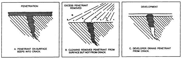
Figure 7-60.-Liquid penetrant inspection. materials and to make sure that the surface is entirely dry before using the liquid penetrant. Maintain the temperature of the inspection piece and the liquid penetrant in the range of 50F to 100F. Do not attempt to use the liquid penetrant when this temperature range cannot be maintained. Do not use an open flame to increase the temperature because some of the liquid penetrant materials are flammable. After thoroughly cleaning and drying the surface, coat the surface with the liquid penetrant. Spray or brush on the penetrant or dip the entire piece into the penetrant. To allow time for the penetrant to soak into all the cracks, crevices, or other defects that are open to the surface, keep the surface of the piece wet with the penetrant for a minimum of 15 or 30 minutes, depending upon the penetrant being used. After keeping the surface wet with the penetrant for the required length of time, remove any excess penetrant from the surface with a clean, dry cloth, or absorbent paper towel. Then dampen a clean, lint-free material with penetrant remover and wipe the remaining excess penetrant from the test surface. Next, allow the test surface to dry by normal evaporation or wipe it dry with a clean, lint-free absorbent material. In drying the surface, avoid contaminating it with oil, lint, dust, or other materials that would interfere with the inspection. After the surface has dried, apply another substance, called a developer. Allow the developer (powder or liquid) to stay on the surface for a minimum of 7 minutes before starting the inspection. Leave it on no longer than 30 minutes, thus allowing a total of 23 minutes to evaluate the results. The following actions take place when using dye penetrants. First, the penetrant that is applied to the surface of the material will seep into any passageway open to the surface, as shown in figure 7-60, view A. The penetrant is normally red in color, and like penetrating oil, it seeps into any crack or crevice that is open to the surface. Next, the excess penetrant is removed from the surface of the metal with the penetrant remover and a lint-free absorbent material. Only the penetrant on top of the metal surface is removed (fig. 7-60, view B), leaving the penetrant that has seeped into the defect. Finally, the white developer is applied to the surface of the metal, as shown in figure 7-60, view C. The developer is an absorbing material that actually draws the penetrant from the defect. Therefore, the red penetrant indications in the white developer represent the defective areas. The amount of red penetrant drawn from the defective areas indicates the size and sometimes the type of defect. When you use dye penetrants, the lighting in the test area must be bright enough to enable you to see any indications of defects on the test surface. The indications you see during a liquid penetrant inspection must be carefully interpreted and evaluated. In almost every inspection, some insignificant indications are present. Most of these are the result of the failure to remove all the excess penetrant from the surface. At least 10 percent of all indications must be removed from the surface to determine whether defects are actually present or whether the indications are the result of excess penetrant. When a second inspection does not reveal indications in the same locations, it is usually safe to assume that the first indications were false. Remove all penetrant inspection materials as soon as possible after the final inspection has been made. Use water or solvents, as appropriate. Since some of the liquid penetrant materials are flammable, do not use them near open flames, and do not apply them to any surface that is at a temperature higher than 100F. In addition to being flammable, many solvents are poisonous in the vapor form and highly imitating to the skin in the liquid form. Radiographic Inspection Radiographic inspection is a method of inspecting weldments by the use of rays that penetrate through the welds. X rays or gamma rays are the two types of waves used for this process. The rays pass through the weld and onto a sensitized film that is in direct contact with the back of the weld. When the film is developed, gas pockets, slag inclusions, cracks, or poor penetration will be visible on the film. Because of the danger of these rays, only qualified personnel are authorized to perform these tests. As Seabees, you will rarely come in contact with these procedures. Ultrasonic Inspection Ultrasonic inspection of testing uses high-frequency vibrations or waves to locate and measure defects in welds. It can be used in both ferrous and nonferrous materials. This is an extremely sensitive system and can locate very fine surface and subsurface cracks as well as other types of defects. All types of joints can be tested. This process uses high-frequency impulses to check the soundness of the weld. In a good weld, the signal travels through the weld to the other side and is then reflected back and shown on a calibrated screen. Irregularities, such as gas pockets or slag inclusions, cause the signal to reflect back sooner and will be displayed on the screen as a change in depth. When you use this system, most all types of materials can be checked for defects. Another advantage of this system is that only one side of the weld needs to be exposed for testing. Eddy Current Testing Eddy current is another type of testing that uses electromagnetic energy to detect faults in weld deposits and is effective for both ferrous and nonferrous materials. As a Seabee, you will rarely use this type of testing in the field. Eddy current testing operates on the principle that whenever a coil carrying a high-frequency alternating current is placed next to a metal, an electrical current is produced in the metal by induction. This induced current is called an eddy current. The test piece is exposed to electromagnetic energy by being placed in or near high-frequency ac current coils. The differences in the weld cause changes in the impedance of the coil, and this is indicated on electronic instruments. When there are defects, they show up as a change in impedance, and the size of the defect is shown by the amount of this change. |
|
Privacy Statement - Press Release - Copyright Information. - Contact Us - Support Integrated Publishing |