 |
||
|
|
||
| |||||||||||||||
|
|
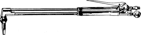
CUTTING TORCHES The equipment and accessories for oxygas cutting are the same as for oxygas welding except that you use a cutting torch or a cutting attachment instead of a welding torch. The main difference between the cutting torch and the welding torch is that the cutting torch has
Figure 4-11.-One piece oxygas cutting torch.
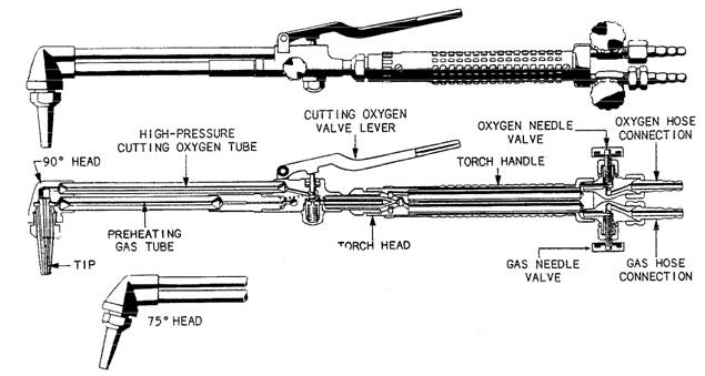
Figure 4-12.-Cutting attachment for combination torch. an additional tube for high-pressure cutting oxygen.The flow of high-pressure oxygen is controlled from a valve on the handle of the cutting torch. In the standard cutting torch, the valve may be in the form of a trigger assembly like the one in figure 4-11. On most torches, the cutting oxygen mechanism is designed so the cutting oxygen can be turned on gradually. The gradual opening of the cutting oxygen valve is particularly helpful in operations, such as hole piercing and rivet cutting. Torch Body Most welding torches are designed so the body of the torch can accept either welding tips or a cutting attachment. This type of torch is called a combination torch. The advantage of this type of torch is the ease in changing from the welding mode to the cutting mode. There is no need to disconnect the hoses; you just unscrew the welding tip and then screw on the cutting attachment. The high-pressure cutting oxygen is controlled by a lever on the torch handle, as shown in figure 4-12. Cutting Torch Tips As in welding, you must use the proper size cutting tip if quality work is to be done. The preheat flames must furnish just the right amount of heat, and the oxygen jet orifice must deliver the correct amount of oxygen at just the right pressure and velocity to produce a clean cut. All of this must be done with a minimum consumption of oxygen and fuel gases. Careless workers and workers not acquainted with the correct procedures waste both oxygen and fuel gas. This does not seem important when you are working in a shop, but if you are deployed, it
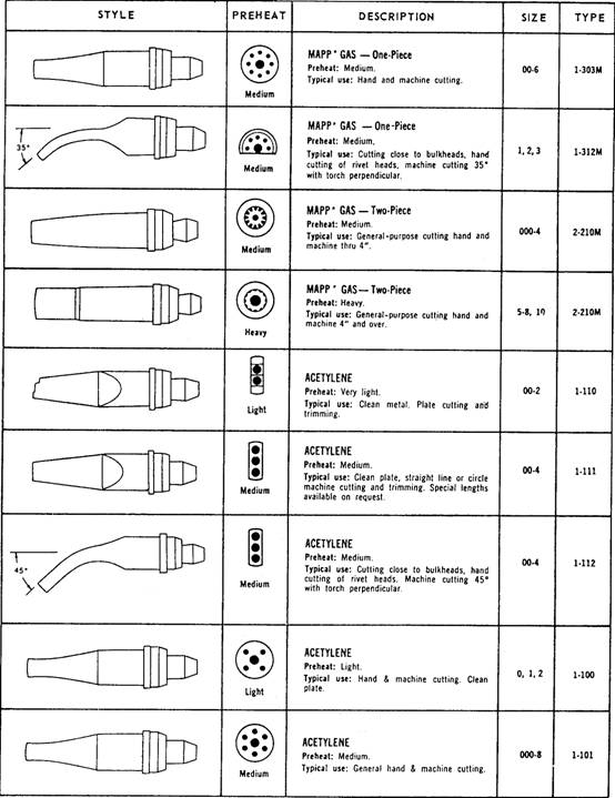
Figure 4-13.-Common cutting torch tips and their uses. becomes critical due to the long lead time between resupply. Each manufacturer makes many different types of cutting tips. Although the orifice arrangements and the tip material are much the same among the manufacturers, the part of the tip that fits into the torch head often differs in design. Because of the way the Navy purchases its cutting and welding equipment, there is the possibility of having two or three different types of cutting torches in your kits. Make sure that the cutting tips match the cutting attachment and ensure that the cutting attachment matches the torch body. Figure 4-13 shows the different styles of tips, their orifice arrangements, and their uses. The tips and seats are designed to
Figure 4-14.-Four cutting-tip conditions. produce a even flow of gas and to keep themselves as cool as possible. The seats must produce leakproof joints. If the joints leak, the preheat gases could mix with the cutting oxygen or escape to the atmosphere, resulting in poor cuts or the possibility of flashbacks. To make clean and economical cuts, you must keep the tip orifices and passages clean and free of burrs and slag. If the tips become dirty or misshapened, they should be put aside for restoration. Figure 4-14 shows four tips: one that is repairable, two that need replacing, and one in good condition. Since it is extremely important that the sealing surfaces be clean and free of scratches or burrs, store the tips in a container that cannot scratch the seats. Aluminum racks, plastic racks, and wood racks or boxes make ideal storage containers. TIP MAINTENANCE.- In cutting operations, the stream of cutting oxygen sometimes blows slag and molten metal into the tip orifices which partially clogs them. When this happens, you should clean the orifices thoroughly before you use the tip again. A small amount of slag or metal in an orifice will seriously interfere with the cutting operation. You should follow the recommendations of the torch manufacturer as to the size of drill or tip cleaner to use for cleaning the orifices. If you do not have a tip cleaner or drill, you may use a piece of soft copper wire. Do not use twist drills, nails, or welding rods for cleaning tips because these items are likely to enlarge and distort the orifices. Clean the orifices of the cutting torch tip in the same manner as the single orifice of the welding torch tip. Remember: the proper technique for cleaning the tips is to push the cleaner straight in and out of the orifice. Be careful not to turn or twist the cleaning wire. Figure 4-15 shows a typical set of tip cleaners. Occasionally the cleaning of the tips causes enlargement and distortion of the orifices, even when using the proper tip cleaners. If the orifices become enlarged, you will get shorter and thicker preheating flames; in addition, the jet of cutting oxygen will spread, rather than leave the torch, in the form of a long, thin stream. If the orifices become belled for a short distance at the end, you can sometimes correct this by rubbing the tip back and forth against emery cloth placed on a flat surface. This action wears down the end of the tip where the orifices have been belled, thus bringing the orifices back to their original size. Obviously, this procedure will not work if the damage is great or if the belling extends more than a slight distance into the orifice. After reconditioning a tip, you may test it by lighting the torch and observing the preheating flames. If the
Figure 4-15.-Tip cleaners.
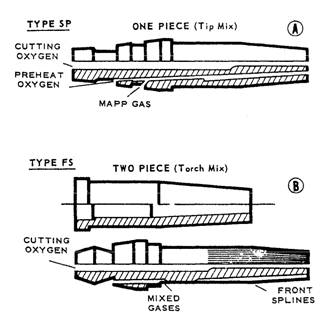
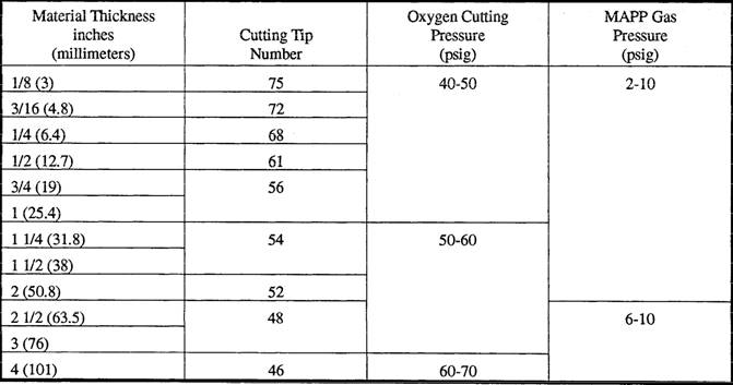
Figure 4-16.-MAPP gas cutting tips. flames are too short, the orifices are still partially blocked. If the flames snap out when you close the valves, the orifices are still distorted. If the tip seat is dirty or scaled and does not properly fit into the torch head, heat the tip to a dull red and quench it in water. This will loosen the scale and dirt enough so you can rub it off with a soft cloth. MAPP GAS CUTTING TIPS.- Four basic types of MAPP gas cutting tips are used: two are for use with standard pressures and normal cutting speeds, and two are for use with high pressures and high cutting speeds. Only the standard pressure tips, types SP and FS, will be covered here since they are the ones that Steelworkers will most likely use. SP stands for standard pressure and FS for fine standard. The SP tip (fig. 4-16, view A) is a one-piece standard pressure tip. It is used for cutting by hand, especially by welders who are accustomed to one-piece tips. SP tips are more likely to be used in situations where MAPP gas is replacing acetylene as the fuel gas. The FS tip (fig. 4-16, view B) is a two-piece, fine spline, standard pressure tip. It is used for cutting by hand as well as by machine. Welders accustomed to two-piece cutting tips will use them in hand cutting, especially when MAPP gas is replacing natural gas or propane as the fuel gas. The FS tips will produce heavier preheating flames and faster starts than the SP tips; however, two-piece tips will not take as much thermal or physical abuse as one-piece tips. But in the hands of skilled Steelworkers, they should last as long as onepiece tips. Recommended tip sizes and gas pressures for use in cutting different thicknesses of steel using MAPP gas as a fuel are given in table 4-1. Table 4-1.-Recommended MAPP Gas Tip Sizes and Oxyfuel Pressures
|
|
Privacy Statement - Press Release - Copyright Information. - Contact Us - Support Integrated Publishing |