 |
||
|
|
||
| |||||||||||||||
|
|
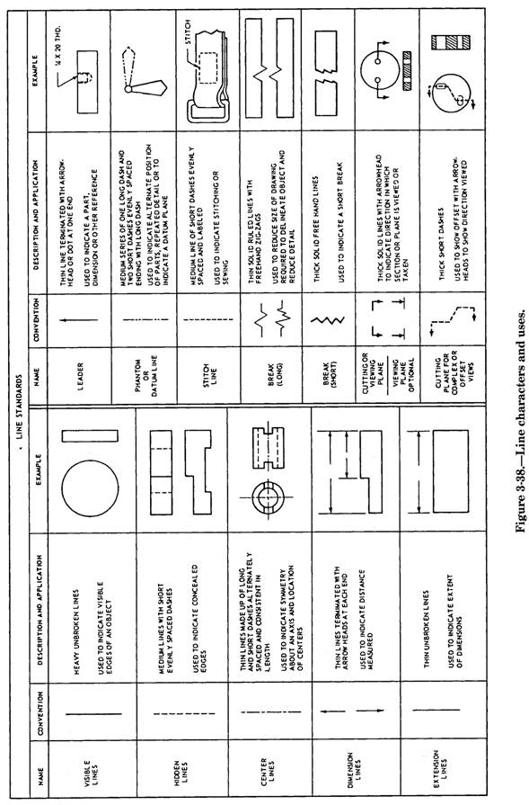
READING DRAWINGS To read a drawing, you must know how engineers use lines, dimensions, and notes to communicate their ideas on paper. In this section, we briefly discuss each of these drawing elements. For a more thorough discussion, refer to publications, such as Blueprint Reading and Sketching, NAVEDTRA 10077-F1, or to Engineering Aid 3, NAVEDTRA 10696. Lines Figure 3-38 shows many of the different types of lines that are used in drawings. You can see that each line has a specific meaning you must understand to interpret a drawing correctly. Let's discuss a few of the most important types. A visible line (sometimes called object line) is used to show the edges of an object that are visible to the viewer. For example, if you look at one of the walls of the room you are in, you can see the outline of the walls and (depending on the wall you are looking at) the outline of doors and windows. On a drawing, these visible outlines or edges can be shown using visible lines that are drawn as described in figure 3-38. Now look at the wall again. Assuming that the wall is wood frame, you know that there are studs or framing members inside the wall that you cannot see. Also, the wall may contain other items, such as water pipes and electrical conduit, that you also cannot see. On a drawing, the edges of those concealed studs and other items can be shown using hidden lines (fig. 3-38). These lines are commonly used in drawings. As you can imagine, the more hidden lines there are, the more difficult it becomes to decipher what is what; however, there is another way these studs and other items can be "seen." Imagine that you "cut away" the wallboard that covers the wall and replace it with a sheet of clear plastic. That clear plastic can be thought of as a cutting or viewing plane (fig. 3-38) through which the previously concealed studs, piping, and conduit are now visible. Now those items can be drawn using visible lines, rather than hidden lines. A view of this type is called a sectional view, and a drawing of the view is called a section drawing. Section drawings are commonly used to show the internal components of a complicated object. Many times, you will see lines drawn on the visible surfaces of a section drawing. These lines, called section lines, are used to show different types of materials.
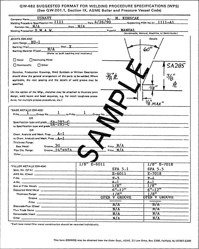
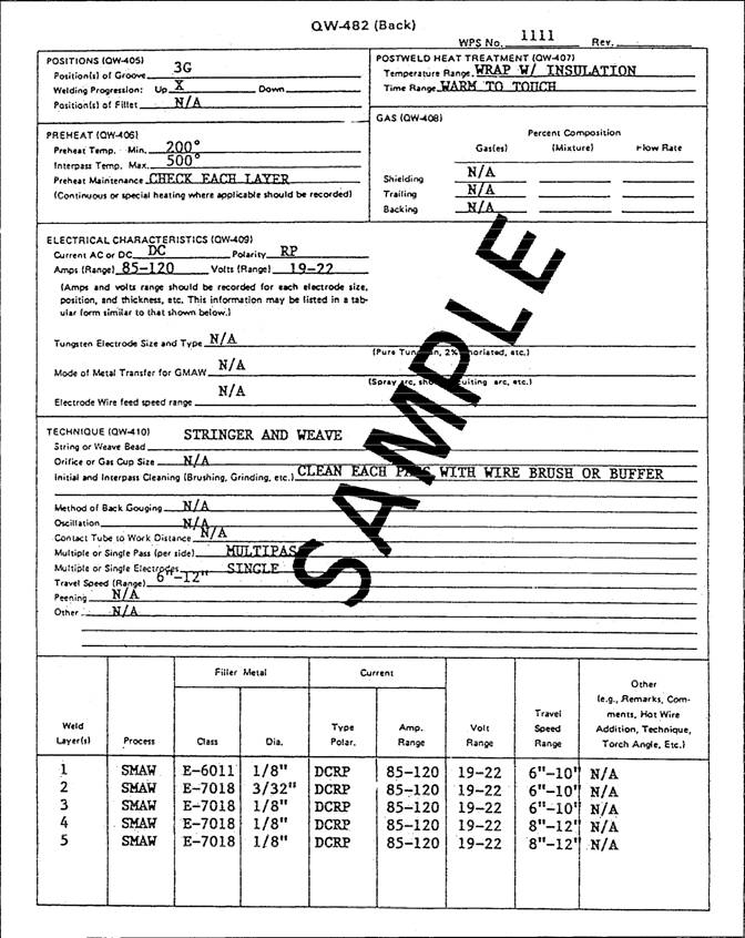
Figure 3-37.-Welding procedure specification.
Figure 3-37.-Welding procedure specification-Continued.
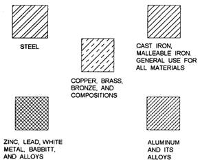
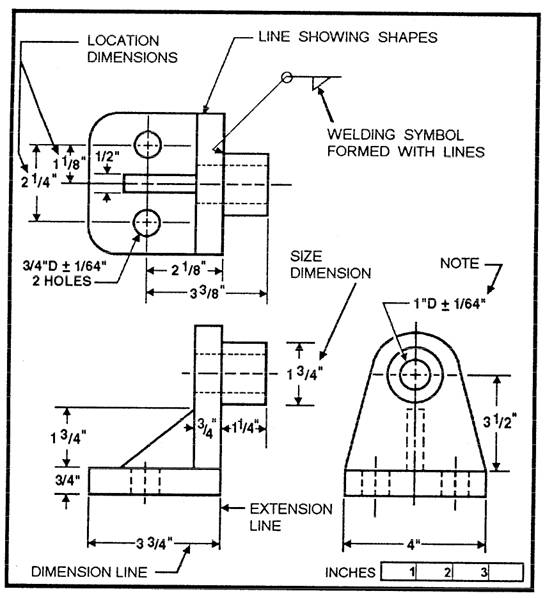
Figure 3-39.-Section lines for various metals. Some of the types of section lines you are likely to encounter as a welder are shown in figure 3-39. Another use of lines is to form symbols, such as welding symbols, that are discussed later in this chapter. Dimensions While engineers use lines to describe the shape or form of an object, they use dimensions to provide a complete size description. Dimensions used on drawings are of two types: size and location. As implied by their names, a size dimension shows the size of an object or parts of an object and a location dimension is used to describe the location of features. Examples of both size and location dimensions are shown in figure 3-40.
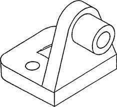
Figure 3-40.-Elements of an orthographic drawing. While on the subject of dimensions, it should be noted that large objects are seldom drawn to their true size. Instead, the engineer or draftsman reduces the size of the object "to scale." For example, when drawing a 40-foot tower, the drawing may be prepared using a scale of 1/2"= 1'-0". In this case, the height of the tower, on paper, is 20 inches. The scale used to prepare working drawings is always noted on the drawing. It maybe a fractional scale, such as discussed here, or a graphic scale, such as the one shown in figure 3-40. In the Navy, both numerical and graphic scales are usually shown on construction drawings. When you are using a drawing, the dimensions of an object should never be measured (scaled) directly from the drawing. These measurements are frequently inaccurate, since a change in atmospheric conditions causes drawing paper to shrink or expand. To ensure accuracy, always use the size and location dimensions shown on the drawing. If a needed dimension is not shown on the drawing, you should check the graphic scale, since it will always shrink or expand at the same rate as the drawing paper. Notes Drawing notes are used for different purposes and are either general or specific in nature. One example of how notes are used are the two notes shown in figure 3-40 that give the inside diameters of the holes. As you can see, these notes are used for size dimensioning. They are specific notes in that, by using a leader line, each note is referred to a specific hole or set of holes. A general note is used to provide additional information that does not apply to any one particular part or feature of the drawing. For example, the drawing shown in figure 3-40 could contain a general note saying: "All holes shall be reamed using a tolerance of 1/64 inch." Drawing Views Look at the drawing shown in figure 3-41. This type of drawing is called a pictorial drawing. These drawings are frequently used to show how an object should appear after it is manufactured. Pictorial drawings are used as working drawings for a simple item, such as a metal washer. For a more complex object, as shown in figure 3-41, it becomes too difficult to provide a complete description in a pictorial drawing. In this case, it is common practice to prepare orthographic drawings to describe the object fully.
Figure 3-41.-Pictorial drawing of a steel part.
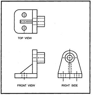
Figure 3-42.-Three-view orthographic drawing of the steel part shown in figure 3-41. Assume you are holding the object shown in figure 3-41 in your hands. When you hold the object so you are looking directly at the top face of the object, the view you see is the top view. A drawing of that view is called an orthographic drawing. Obviously, an orthographic drawing of only the top view of the object is insufficient to describe the entire object; therefore, additional orthographic drawings of one or more of the other faces of the object are necessary. The number of orthographic views needed to describe an object fully depends upon the complexity of the object. For example, a simple metal washer can be fully described using only one orthographic view; however, an extremely complex object may require as many as
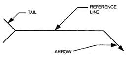
Figure 3-43.-Standard welding symbol. six views (top, front, left side, right side, back, and bottom). Most objects, such as the steel part shown in figure 3-41, can be sufficiently described using three views: top, front, and right side. For the object shown in figure 3-41, orthographic drawings of the top, front, and right-side views are shown in figure 3-42. Notice the placement of the views shown in figure 3-42. This is a standard practice that you should be aware of when reading orthographic drawings. By this standard practice, the top view is always placed above the front view and the right-side view is placed to the right of the front view. When additional views are needed, the left side is always drawn to the left of the front view and the bottom is drawn below the front view. Placement of the back view is somewhat flexible; however, it is usually drawn to the left of the left-side view. When reading and understanding the different orthographic views, you find it is sometimes helpful to prepare a pictorial sketch. You can find a discussion of sketching in Blueprint Reading and Sketching, NAVEDTRA 10077-Fl. Think of drawings as a form of communication. They are intended to help you understand all the necessary information you need to fabricate and assemble an object regardless of the complexity. It is important that you learn to read drawings. Handling and Care of Drawings Special care should be exercised in the handling of drawings. When they are not being used, keep them on a rack or in another assigned place of storage. Drawings are valuable, and they may be difficult or impossible to replace if they are lost or damaged. Now, we will discuss some special symbols. These are symbols a welder must be able to read and to understand how they are used to convey information. |
|
Privacy Statement - Press Release - Copyright Information. - Contact Us - Support Integrated Publishing |