Custom Search
|
|
  |
|
|
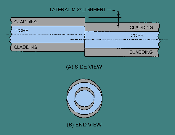
SUMMARY Now that you have completed this chapter, let's review some of the new terms, concepts, and ideas you have learned. You should have a thorough understanding of these principles before moving on to chapter 5. FIBER OPTIC CONNECTIONS transfer optical power from one component to another. Fiber optic connections also permit fiber optic systems to be more than just a point-to-point data link. A FIBER OPTIC SPLICE is a permanent joint between two fibers or two groups of fibers. FIBER OPTIC CONNECTORS permit easy coupling and uncoupling of optical fibers. FIBER OPTIC COUPLERS distribute or combine optical signals between fibers. POOR FIBER END PREPARATION and <emphasis type="b.GIF">POOR FIBER ALIGNMENT</emphasis> are the main causes of coupling loss. RADIANCE is the amount of optical power emitted by a unit area of emitting surface per unit time in a specified direction. An optical source's radiance, or brightness, is a measure of its optical power launching capability. FIBER-TO-FIBER COUPLING LOSS is affected by intrinsic and extrinsic coupling losses. INTRINSIC COUPLING LOSSES are caused by inherent fiber characteristics. EXTRINSIC COUPLING LOSSES are caused by jointing techniques. A FIBER PIGTAIL is a short length of optical fiber (usually 1 meter or less) permanently fixed to a fiber optic component, such as an optical source or detector. FRESNEL REFLECTION occurs twice in a fiber-to-fiber connection. A portion of the optical power is reflected when the light first exits the source fiber. Light is then reflected as the optical signal enters the receiving fiber. INDEX MATCHING GEL eliminates or reduces the step change in the refractive index at the fiber interface, reducing Fresnel reflection. POOR FIBER ALIGNMENT is a main source of coupling loss in fiber-to-fiber connections. The three basic coupling errors that occur during fiber alignment are fiber separation (longitudinal misalignment), lateral misalignment, and angular misalignment. In FIBER SEPARATION a small gap remains between fiber-end faces after completing the fiber connection. LATERAL, or AXIAL, MISALIGNMENT is when the axes of the two fibers are offset in a perpendicular direction. ANGULAR MISALIGNMENT is when the axes of the two fibers are no longer parallel.
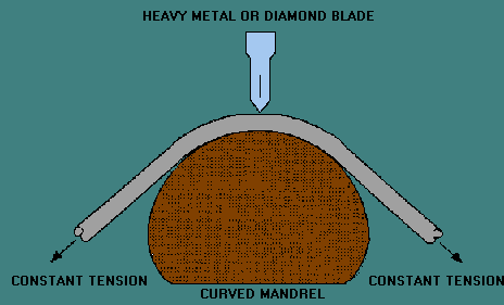
SINGLE MODE FIBERS are more sensitive to alignment errors than multimode fibers because of their small core diameters and low numerical apertures. The MODE POWER DISTRIBUTION (MPD) is the distribution of radiant power among the various modes propagating along the optical fiber. Poor FIBER END PREPARATION is another source of extrinsic coupling loss. An optical fiber end face must be flat, smooth, and perpendicular to the fiber's axis to ensure proper fiber connection. The SCORE-AND-BREAK method is the basic fiber cleaving technique for preparing optical fibers for coupling.
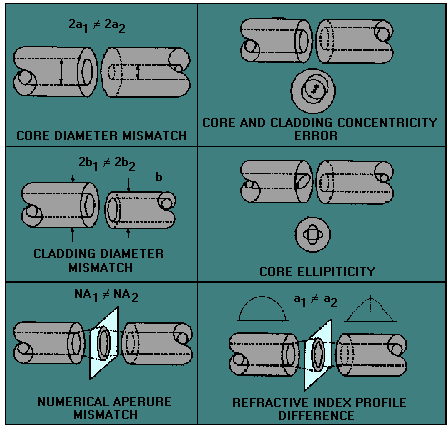
POLISHING the fiber ends removes most surface imperfections introduced by the fiber cleaving or cutting process. Fiber polishing involves a step-down approach. The first step is to give the surface of the fiber end a rough polish. The next step involves giving the surface of the fiber end a fine polish. FIBER MISMATCHES are a source of intrinsic coupling loss. Types of fiber mismatches include fiber geometry mismatches, NA mismatch, and refractive index profile difference. FIBER GEOMETRY MISMATCHES include core diameter, cladding diameter, core ellipticity, and core-cladding concentricity differences.
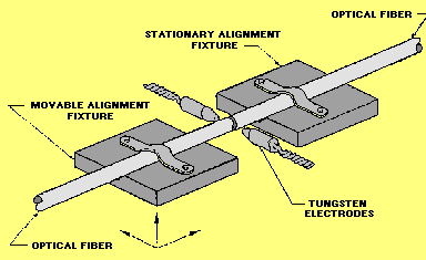
CORE DIAMETER MISMATCH causes coupling loss only if the launching fiber has a larger core radius than the receiving fiber. NA MISMATCH causes coupling loss only if the launching fiber has a higher NA than the receiving fiber. A REFRACTIVE INDEX PROFILE DIFFERENCE causes coupling loss only if the launching fiber has a larger profile parameter than the receiving fiber. MECHANICAL and FUSION SPLICING are two broad categories that describe the techniques used for fiber splicing. A mechanical splice is a fiber splice where mechanical fixtures perform fiber alignment and connection. A fusion splice is a fiber splice where localized heat fuses or melts the ends of two lengths of optical fiber together. In MECHANICAL SPLICING, mechanical fixtures hold the two optical fibers in alignment for an indefinite period of time without movement. The amount of splice loss is stable over time and unaffected by changes in environmental or mechanical conditions. ARC FUSION involves the discharge of electric current across a gap between two electrodes. By placing the fiber end between the electrodes, the electric discharge melts or fuses the ends of the fibers.
PREFUSION involves a short discharge of electric current across the gap between the electrodes. In prefusion the fiber ends are cleaned and rounded to eliminate any surface defects that remain from fiber cleaving. A FIBER OPTIC CONNECTOR is a demateable device that permits the coupling of optical power between two optical fibers or two groups of fibers. FIBER ALIGNMENT in a fiber optic connector is the critical parameter in maintaining total insertion loss below the required level. FIBER OPTIC CONNECTORS can affect system performance by increasing modal and reflection noise. MODAL NOISE is eliminated by using only single mode fiber with laser sources and only low-coherence sources such as light-emitting diodes with multimode fiber. REFLECTION NOISE is reduced by index matching gels, physical contact polishes, or antireflection coatings. BUTT-JOINTED and EXPANDED BEAM CONNECTORS are two ways to classify fiber optic connectors. Butt-jointed connectors bring the prepared ends of two fibers into close contact. Expanded beam connectors use two lenses to first expand and then refocus the light from the transmitting fiber into the receiving fiber. LIGHT-DUTY and HEAVY-DUTY CONNECTORS are two ways that the Navy classifies fiber optic connectors. Light-duty connector shipboard applications include locations that protect the connectors from the environment such as in a junction box. Heavy-duty applications require a very rugged, stand-alone, sealed connector. A PASSIVE COUPLER redistributes an optical signal without optical to electrical conversion. An OPTICAL SPLITTER is a passive device that splits the optical power carried by a single input fiber into two output fibers. An OPTICAL COMBINER is a passive device that combines the optical power from two input fibers into a single output fiber. A STAR COUPLER is a passive device that distributes optical power from more than two input ports among several output ports. A TREE COUPLER is a passive device that splits the optical power from one input fiber to more than two output fibers. A tree coupler may also be used to combine the optical power from more than two input fibers into a single output fiber. DIRECTIONAL COUPLERS are fiber optic couplers that prevent the transfer of optical power from one input fiber to another input fiber. A SYMMETRICAL COUPLER transmits the same amount of power through the coupler when the input and output fibers are reversed. |
 
|