Custom Search
|
|
  |
|
|
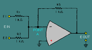
APPLICATIONS OF OPERATIONAL AMPLIFIERS Operational amplifiers are used in so many different ways that it is not possible to describe all of the applications. Entire books have been written on the subject of operational amplifiers. Some books are devoted entirely to the applications of operational amplifiers and are not concerned with the theory of operation or other circuits at all. This module, as introductory material on operational amplifiers, will show you only two common applications of the operational amplifier: the summing amplifier and the difference amplifier. For ease of explanation the circuits shown for these applications will be explained with d.c. inputs and outputs, but the circuit will work as well with a.c. signals. Summing Amplifier (Adder) Figure 3-20 is the schematic of a two-input adder which uses an operational amplifier. The output level is determined by adding the input signals together (although the output signal will be of opposite polarity compared to the sum of the input signals). Figure 3-20. - Two-input adder.
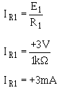
If the signal on input number one (E1) is +3 volts and the signal on input number two (E2) is +4 volts, the output signal (Eout) should be -7 volts [(+3 V) + (+4 V) = +7 V and change the polarity to get -7 V]. With +3 volts at E1 and 0 volts at point A (which is at virtual ground), the current through R1 must be 3 milliamperes. Mathematically:
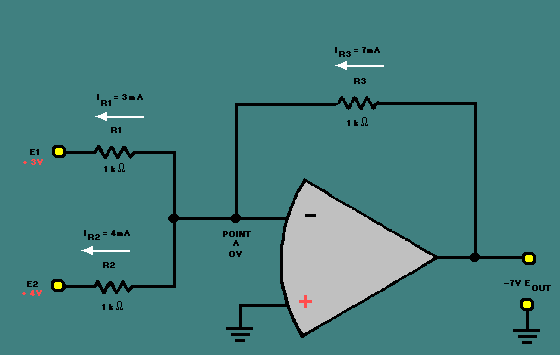
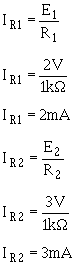
(The + sign indicates a current flow from right to left.) By the same sort of calculation, with +4 volts at E2 and 0 volts at point A the current through R2 must be 4 milliamps. This means that a total of 7 milliamps is flowing from point A through R1 and R2. If 7 milliamps is flowing from point A, then 7 milliamps must be flowing into point A. The 7 milliamps flowing into point A flows through R3 causing 7 volts to be developed across R3. With point A at 0 volts and 7 volts developed across R3, the voltage potential at Eout must be a -7 volts. Figure 3-21 shows these voltages and currents. Figure 3-21. - Current and voltage in a two-input adder.
An adder circuit is not restricted to two inputs. By adding resistors in parallel to the input terminals, any number of inputs can be used. The adder circuit will always produce an output that is equal to the sum of the input signals but opposite in polarity. Figure 3-22 shows a five-input adder circuit with voltages and currents indicated. Figure 3-22. - Five-input adder.
The previous circuits have been adders, but there are other types of summing amplifiers. A summing amplifier can be designed to amplify the results of adding the input signals. This type of circuit actually multiplies the sum of the inputs by the gain of the circuit. Mathematically (for a three-input circuit):
If the circuit gain is -10:
The gain of the circuit is determined by the ratio between the feedback resistor and the input resistors. To change figure 3-20 to a summing amplifier with a gain of -10, you would replace the feedback resistor (R3) with a 10-kilohm resistor. This new circuit is shown in figure 3-23. Figure 3-23. - Summing amplifier.
If this circuit is designed correctly and the input voltages (E1 and E2) are +2 volts and +3 volts, respectively, the output voltage (E out) should be:
To see if this output (-50 V) is what the circuit will produce with the inputs given above, start by calculating the currents through the input resistors, R1 and R2 (remember that point A is at virtual ground):
Next, calculate the current through the feedback resistor (R3):
(The minus sign indicates current flow from left to right.) Finally, calculate the voltage dropped across R3 (which must equal the output voltage):
As you can see, this circuit performs the function of adding the inputs together and multiplying the result by the gain of the circuit. |
 
|
|
|
Integrated Publishing, Inc. - A (SDVOSB) Service Disabled Veteran Owned Small Business
|