Custom Search
|
|
  |
|
|
SUMMARY This chapter has provided you with basic information on circuit control devices. The following is a summary of the main points in this chapter. CIRCUIT CONTROL DEVICES are used to apply or remove power and to select a function or circuit within a device. A SWITCH is one type of circuit control device. Switches are classified in many different ways.
A MANUAL SWITCH must be tuned ON or OFF by a person. An AUTOMATIC SWITCH will turn a circuit ON or OFF without the action of a person by using mechanical or electrical devices. MULTICONTACT SWITCHES make possible the control of more than one circuit or the selection of one of several possible circuits with a single switch.
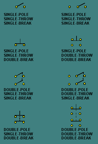
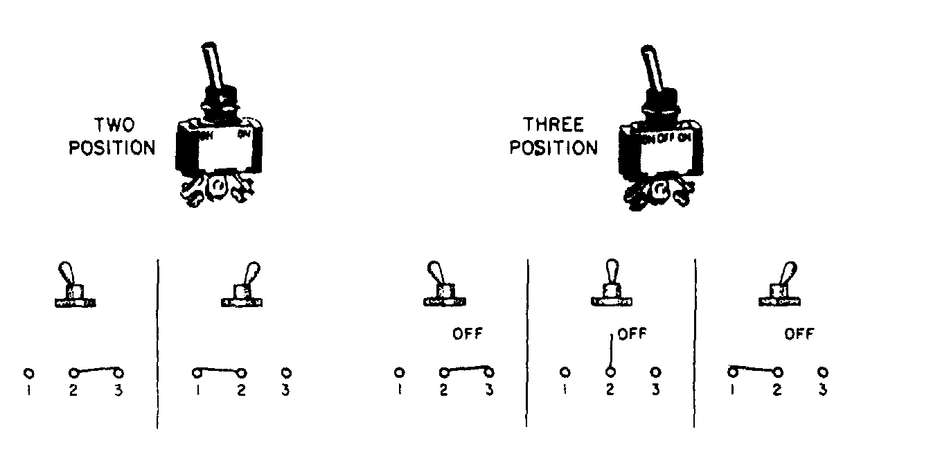
THE POLES of a switch are the points at which current can enter the switch. The number of THROWS is the number of possible circuits that can be connected to each pole. The number of BREAKS is the number of points at which the switch breaks the circuit.
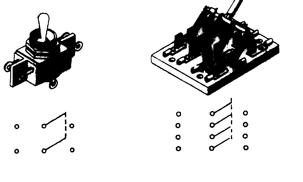
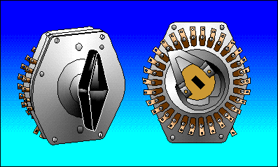
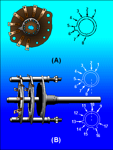
A ROTARY SWITCH is a multicontact switch with contacts arranged in a circular or semicircular manner.
A WAFER SWITCH is a rotary switch in which the contacts are on wafers. The wafers are mechanically connected by the shaft of the switch.
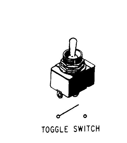
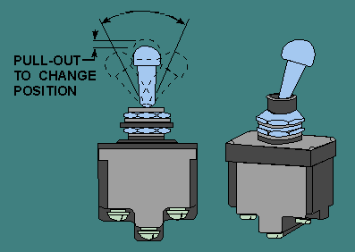
THE ACTUATOR of a switch is the portion of the switch which is moved to cause the switch to change contact positions. The actuator could be a toggle, a pushbutton, a rocker, or, in the case of a rotary switch, a shaft and handle. THE NUMBER OF POSITIONS of a switch refers to the number of points at which the actuator can select a contact configuration.
A MOMENTARY POSITION of a switch is one in which the actuator will only stay as long as force is applied to the actuator. When the force is removed, the actuator (and switch) will return to a non-momentary position. A LOCKED POSITION of a switch is used to prevent the accidental movement of the actuator to or from a specific position.
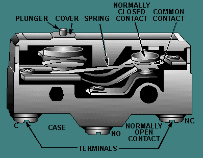
A SNAP-ACTING SWITCH is one in which the movement of the switch contacts is relatively independent of the actuator movement. This is accomplished by using a leaf spring for the common contact of the switch. A MICROSWITCH is an accurate snap-acting switch and the operating point is preset and very accurately known.
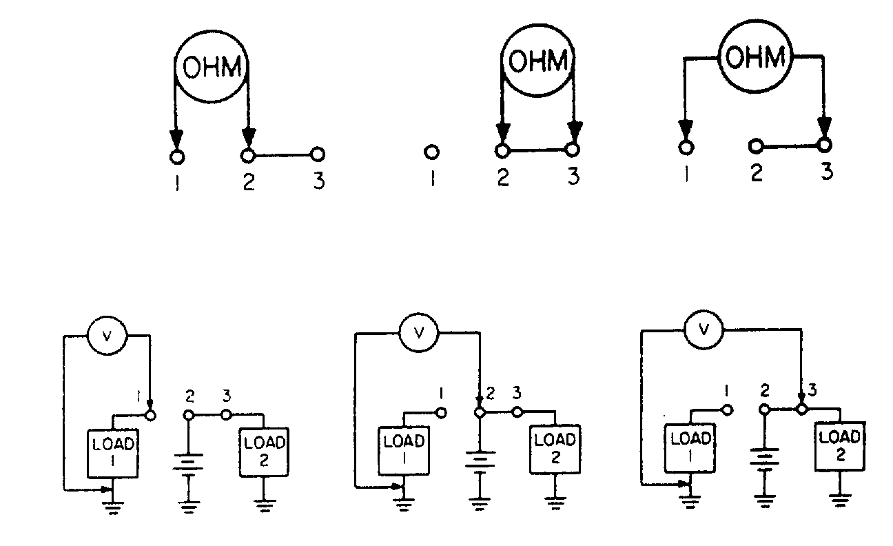
THE VOLTAGE RATING of a switch is the maximum voltage the switch is designed to control. A voltage higher than the voltage rating may be able to "jump" the open contacts of the switch. THE CURRENT RATING of a switch is the maximum current the switch is designed to carry; it is dependent on the voltage rating. Any current higher than the current rating may cause the contacts of the switch to melt and "weld" together. The contacts of a switch can be checked with an ohmmeter if power is removed or with a voltmeter if power is applied to the switch. To check a switch, the actuator should be checked for smooth and correct operation, the terminals should be checked for evidence of corrosion, and the physical condition of the switch should be determined. If a substitute switch must be used to replace a faulty switch, the substitute must have all of the following:
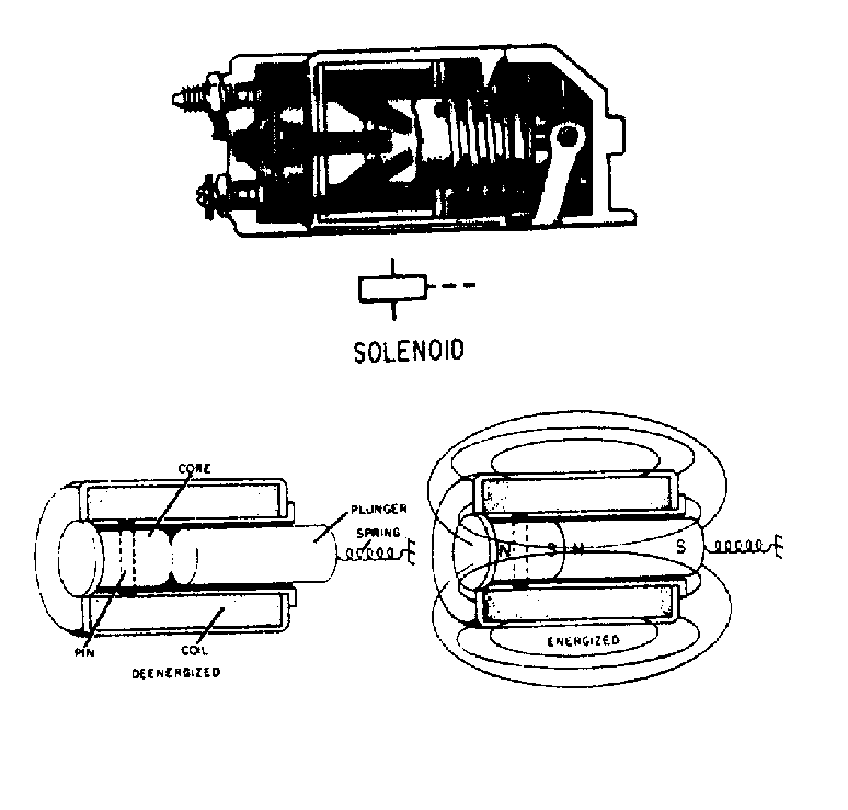
At least the same number of poles, throws, and positions; the same number of breaks and an identical configuration in regard to momentary and locked positions; and a voltage and current rating equal to or higher than the original switch. In addition, the substitute must be of a physical size compatible with the mounting, and must have the same type actuator as the original switch. A SOLENOID is a control device that uses electromagnetism to convert electrical energy into a mechanical motion. The magnetic field of the coil and core will attract the plunger of a solenoid when current flows through the coil. When current is removed, the spring attached to the plunger will cause the plunger to return to its original position. If a solenoid fails to operate, check the terminal connections, the plunger and attached mechanism for smooth operation, the energizing voltage, and the coil of the solenoid.
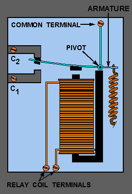
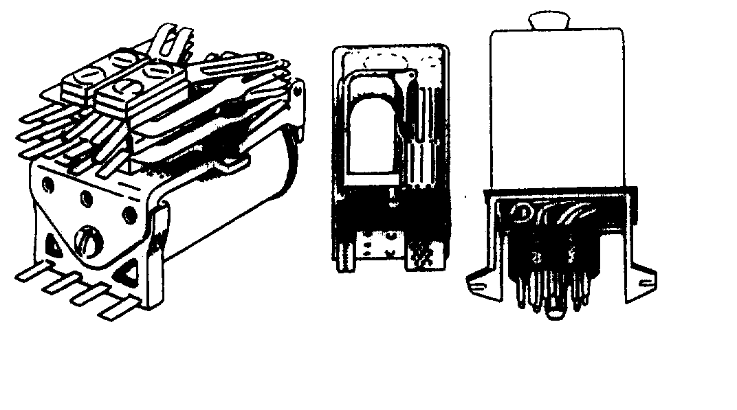
A RELAY is an electromagnetic control device that differs from the solenoid in that the solenoid uses a movable core (plunger) while the relay has fixed core. Relays are classified as CONTROL RELAYS, which control low power COMMON circuits and POWER RELAYS or CONTACTORS which control high power circuits.
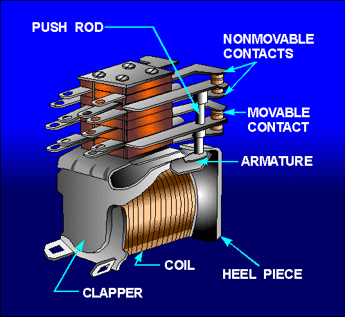
CLAPPER RELAYS use a clapper (armature) to move contact positions and accomplish the switching of circuits.
Relays are described by the type of enclosure. A relay may be OPEN, SEMISEALED, or SEALED.
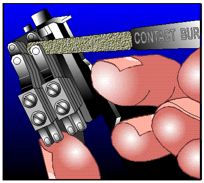
If a relay fails to function, the movement of the contacts should be observed; the coil should be checked for opens or shorts; the terminal leads should be checked for burned or charred insulation; and the contact surfaces should be checked for carbon, arcing, and contact spacing. A BURNISHING TOOL is used to clean the contacts of a relay. Files, sandpaper, and emery cloth should NOT be used.
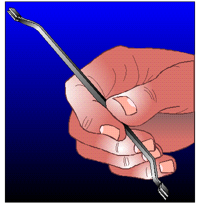
A POINT BENDER is used to adjust contact spacing of a relay. No other tool should be used.
|
 
|