Custom Search
|
|
  |
|
|
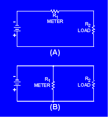
An ammeter is a device that measures current. Since all meter movements have resistance, a resistor will be used to represent a meter in the following explanations. Direct current circuits will be used for simplicity of explanation. AMMETER CONNECTED IN SERIES In figure 1-19(A), R1 and R2 are in series. The total circuit resistance is R2 + R2 and total circuit current flows through both resistors. In figure 1-19(B), R1 and R2 are in parallel. The total circuit resistance is
and total circuit current does not flow through either resistor. Figure 1-19. - A series and a parallel circuit.
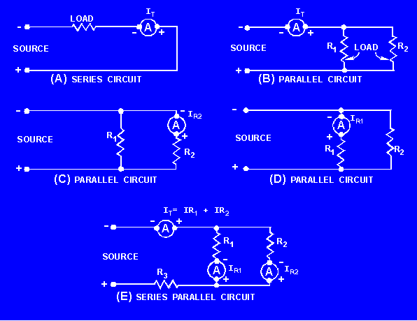
If R1 represents an ammeter, the only way in which total circuit current will flow through the meter (and thus be measured) is to have the meter (R1) in series with the circuit load (R2), as shown in figure 1-19(A). In complex electrical circuits, you are not always concerned with total circuit current. You may be interested in the current through a particular component or group of components. In any case, an ammeter is always connected in series with the circuit you wish to test. Figure 1-20 shows various circuit arrangements with the ammeter(s) properly connected for measuring current in various portions of the circuit.
Figure 1-20. - Proper ammeter connections.
Connecting an ammeter in parallel would give you not only an incorrect measurement, it would also damage the ammeter, because too much current would pass through the meter. EFFECT ON CIRCUIT BEING MEASURED The meter affects the circuit resistance and the circuit current. If R1 is removed from the circuit in figure 1-19(A), the total circuit resistance is R2. Circuit current
With the meter (R1 ) in the circuit, circuit resistance is R1 + R2 and circuit current
The smaller the resistance of the meter (R1), the less it will affect the circuit being measured. (R1 represents the total resistance of the meter; not just the resistance of the meter movement.) |
 
|
|
|
Integrated Publishing, Inc. - A (SDVOSB) Service Disabled Veteran Owned Small Business
|