Custom Search
|
|
  |
|
|
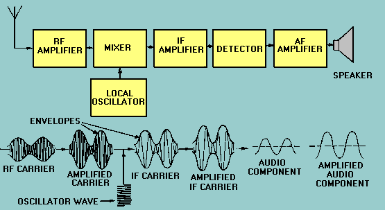
Ship-to-Ship. - Ship-to-ship ssb teletypewriter circuits are in wide use today. Their main application is with task force or task group networks or with several ships in company. By using this type of network, ships can send their outgoing messages to another ship that relays traffic ashore. You can see this procedure saves manpower and circuit time, prevents individual ships from overcrowding ship-to-shore circuits, and conserves the frequency spectrum. Depending on the number and types of ships in company, the guard can be shifted to other ships from time to time. A major advantage of these circuits is that electronic cryptographic devices can be used to send classified messages without need for manual encryption. These circuits are used for incoming as well as outgoing traffic, and they can use either hf or uhf communications equipment. An AM receiver processes amplitude-modulated signals received by its antenna. It delivers an output that is a reproduction of the signal that originally modulated the rf carrier at the transmitter. The signal can then be applied to some reproducing device, such as a loudspeaker, or to a terminal device, such as a teletypewriter. Actual AM receivers vary widely in complexity. Some are very simple; others contain a large number of complex circuits. FUNCTIONS Whatever its degree of sophistication, a receiver must perform certain basic functions to be useful. These functions, in order of their performance, are reception, selection, detection, and reproduction. Reception Reception occurs when a transmitted electromagnetic wave passes through the receiver antenna and induces a voltage in the antenna. Selection Selection is the ability of the receiver to select a particular frequency of a station from all other station frequencies appearing at the antenna of the receiver. Detection Detection is the action of separating the low (audio) frequency intelligence from the high (radio) frequency carrier. A detector circuit is used to accomplish this action. Reproduction Reproduction is the action of converting the electrical signals to sound waves, which can then be interpreted by your ear as speech, music, and the like. An example of this might be the stereo speakers in your car. Sensitivity, noise, selectivity, and fidelity are important receiver characteristics. These characteristics will be useful to you when performing receiver tests. They can help you to determine whether a receiver is working or not or in comparing one receiver to another. Sensitivity The ability of a receiver to reproduce weak signals is a function of the sensitivity of a receiver. The weaker a signal that can be applied to a receiver and still produce a certain value of signal output, the better the sensitivity rating. Sensitivity of a receiver is measured under standardized conditions. It is expressed in terms of the signal voltage, usually in the microvolts that must be applied to the antenna input terminals to give an established level of the output. The output may be an ac or dc voltage measured at the detector output or a power measurement (measured in decibels or watts) at the loudspeaker or headphone terminals. Noise All receivers generate a certain amount of noise, which you must take into account when measuring sensitivity. Receiver noise may originate from the atmosphere (lightning) or from internal components (transistors, tubes). Noise is the limiting factor of sensitivity. You will find sensitivity is the value of input carrier voltage (in microvolts) that must be applied from the signal generator to the receiver input to develop a specified output power. Selectivity Selectivity is the degree of distinction made by the receiver between the desired signal and unwanted signals. You will find the better the ability of the receiver to reject unwanted signals, the better its selectivity. The degree of selection is determined by the sharpness of resonance to which the frequency-determining circuits have been engineered and tuned. You usually measure selectivity by taking a series of sensitivity readings. As you take the readings, you step the input signal along a band of frequencies above and below the circuit resonance of the receiver; for example, 100 kilohertz below to 100 kilohertz above the tuned frequency. As you approach the tuned frequency, the input level required to maintain a given output level will fall. As you pass the tuned frequency, the required input level will rise. Input voltage levels are then compared with frequency. They can be plotted on paper or you might view them on an oscilloscope. They would appear in the form of a response curve. The steepness of the response curve at the tuned frequency indicates the selectivity of the receiver. Fidelity The fidelity of a receiver is its ability to accurately reproduce, in its output, the signal that appears at its input. You will usually find the broader the band passed by frequency selection circuits, the greater your fidelity. You may measure fidelity by modulating an input frequency with a series of audio frequencies; you then plot the output measurements at each step against the audio input frequencies. The resulting curve will show the limits of reproduction. You should remember that good selectivity requires that a receiver pass a narrow frequency band. Good fidelity requires that the receiver pass a broader band to amplify the outermost frequencies of the sidebands. Receivers you find in general use are a compromise between good selectivity and high fidelity. Q.11 What four basic functions must a receiver perform? SUPERHETERODYNE RECEIVER The superheterodyne is the type receiver most familiar to you. You probably see one daily in your home in the form of an AM and/or fm radio. We will discuss the basic workings of both AM and fm types and their differences. Amplitude Modulation Receiver Figure 2-9 shows a block diagram with waveforms of a typical AM superheterodyne receiver developed to overcome the disadvantages of earlier type receivers. Let's assume you are tuning the receiver. When doing this you are actually changing the frequency to which the rf amplifier is tuned. The rf carrier comes in from the antenna and is applied to the rf amplifier. The output of the amplifier is an amplified carrier and is sent to the mixer. The mixer also receives an input from the local oscillator. These two signals are beat together to obtain the IF through the process of heterodyning. (Heterodyning will be further discussed later in this chapter and was covered in NEETS, Module 12, Modulation Principles.) At this time you should note the dotted lines connecting the local oscillator, rf amplifier, and the mixer. This is used on block diagrams and schematics to indicate GANGED TUNING. Ganged tuning is the process used to tune two or more circuits with a single control. In our example, when you change the frequency of the receiver all three stages change by the same amount. There is a fixed difference in frequency between the local oscillator and the rf amplifier at all times. This difference in frequency is the IF. This fixed difference and ganged tuning ensures a constant IF over the frequency range of the receiver. Figure 2-9. - AM superheterodyne receiver and waveforms.
The IF carrier is applied to the IF amplifier. The amplified IF carrier is then sent to the detector. The output of the detector is the audio component of the input signal. This audio component is then passed through an audio frequency amplifier. The amplified audio component is sent to a speaker for reproduction. This allows you to hear the signal. You should note that a superheterodyne receiver may have more than one frequency-converting stage and as many amplifiers as needed to obtain the desired power output. (Additional amplifiers are not shown.) HETERODYNING. - As you know the intermediate frequency is developed by a process called heterodyning. This action takes place in the mixer stage (sometimes called a converter or first detector). Heterodyning is the combining of the incoming signal with the local oscillator signal. When heterodyning the incoming signal and the local oscillator signal in the mixer stage, four frequencies are produced. They are the two basic input frequencies and the sum and the difference of those two frequencies. The amplifier that follows (IF amplifier) will be tuned to the difference frequency. This difference frequency is known as the intermediate frequency (IF). A typical value of IF for an AM communications receiver is 455 kilohertz. The difference frequency is a lower frequency than either the rf input or oscillator frequencies. This lower frequency gives slightly better gain but does increase the chances of image frequency interference. Image frequencies will be discussed later in this chapter. DETECTION. - Once the IF stages have amplified the intermediate frequency to a sufficient level, it is fed to the detector. When the mixer is referred to as the first detector, this stage would be called the second detector. The detector extracts the modulating audio signal. The detector stage consists of a rectifying device and filter, which respond only to the amplitude variations of the IF signal. This develops an output voltage varying at an audio-frequency rate. The output from the detector is further amplified in the audio amplifier and is used to drive a speaker or earphones. Frequency Modulated Receiver The function of a frequency-modulated receiver is the same as that of an AM superheterodyne receiver. You will find some important differences in component construction and circuit design caused by differences in the modulating technique. Figure 2-10 is a block diagram showing waveforms of a typical fm superheterodyne receiver. Comparison of block diagrams in figures 2-9 and 2-10 shows that in both AM and fm receivers, the amplitude of the incoming signal is increased in the rf stages. The mixer combines the incoming rf with the local oscillator signal to produce the intermediate frequency, which is then amplified by one or more IF amplifier stages. You should note that the fm receiver has a wide-band IF amplifier. The bandwidth for any type of modulation must be wide enough to receive and pass all the side-frequency components of the modulated signal without distortion. The IF amplifier in an fm receiver must have a broader bandpass than an AM receiver. Figure 2-10. - Block diagram of an fm receiver and waveforms.
Sidebands created by fm differ from the AM system. You should recall that the AM system consists of a single set of side frequencies for each radio-frequency signal modulated. An fm signal inherently occupies a wider bandwidth than AM because the number of extra sidebands that occur in an fm transmission is directly related to the amplitude and frequency of the audio signal. You should observe that only two fundamental sections of the fm receiver are electrically different from the AM receiver. These are the discriminator (detector) and the limiter. Beyond the IF stage, the two receivers have a marked difference. AM demodulation involves the detection of variations in the amplitude of the signal; fm demodulation is the process of detecting variations in the frequency of the signal. In fm receivers a DISCRIMINATOR is a circuit designed to respond to frequency shift variations. A discriminator is preceded by a LIMITER circuit, which limits all signals to the same amplitude level to minimize noise interference. The audio frequency component is then extracted by the discriminator, amplified in the af amplifier, and used to drive the speaker. ADVANTAGES. - In normal reception, fm signals are almost totally absent of static while AM signals are subject to cracking noises and whistles. Fm followed AM in development and has the advantage of operating at a higher frequency where a greater amount of frequencies are available. Fm signals provide much more realistic sound reproduction because of an increase in the number of sidebands. This increase in the number of sidebands allows more of the original audio signal to be transmitted and, therefore, a greater range of frequencies for you to hear. As you can see, fm requires a wide bandpass to transmit signals. Each transmitting station must be assigned a wide band in the fm frequency spectrum. During fm transmissions, the number of significant sidebands that must be transmitted to obtain the desired fidelity is related to the deviation (change in carrier' frequency) divided by the highest audio frequency to be used. At this point you may want to review chapter 2 of NEETS, Module 12, Modulation Principles. For example, if the deviation is 40 kilohertz and the highest audio frequency is 10 kilohertz, the modulation index is figured as shown below:
In this example, a modulation index of 4 equates to 14 significant sidebands. Because the audio frequency is 10 kilohertz and there are 14 side-bands, the bandwidth must accommodate a 140-kilohertz signal. You can see this is considerably wider than the 10-to-15-kilohertz bandpass used in AM transmitting. FREQUENCY CONVERSION. - Frequency conversion is accomplished by using the heterodyne principle of beating two frequencies together to get an intermediate frequency. So far, you have only become familiar with single conversion; however, some receivers use double or triple conversion. These methods are sometimes referred to as double or triple heterodyning. Receivers using double or triple conversion are very selective and suppress IMAGE SIGNALS to yield sharp signal discrimination. (Image signals are undesired, modulated carrier signals that differ by twice the intermediate frequency from the frequency to which the superheterodyne receiver is tuned.) Double and triple conversion receivers also have better adjacent channel selectivity than can be realized in single conversion sets. In military communications receivers you may sacrifice fidelity to improve selectivity. This is permitted because intelligence (voice, teletypewriter) can be carried on a fairly narrow band of frequencies. Entertainment receivers, on the other hand, must reproduce a wider band of frequencies to achieve their high-fidelity objective. Q.13 What frequency conversion principle is used to develop the IF? |
 
|
|
|
Integrated Publishing, Inc. - A (SDVOSB) Service Disabled Veteran Owned Small Business
|