|
PRACTICAL APPLICATION OF VOLTAGE DIVIDERS
In actual practice the computed value of the bleeder resistor does not always come out to an even value. Since the rule-of-thumb for bleeder current is only an estimated value, the bleeder resistor can be of a value close to the computed value. (If the computed value of the resistance were 510 ohms, a 500-ohm resistor could be used.) Once the actual value of the bleeder resistor is selected, the bleeder current must be recomputed. The voltage developed by the bleeder resistor must be equal to the voltage requirement of the load in parallel with the bleeder resistor.
The value of the remaining resistors in the voltage divider is computed from the current through the remaining resistors and the voltage across them. These values must be used to provide the required voltage and current to the loads.
If the computed values for the divider resistors are not even values; series, parallel, or series-parallel networks can be used to provide the required resistance.
Example: A voltage divider is required to supply two loads from a 190.5 volts source. Load 1 requires +45 volts and 210 milliamps; load 2 requires +165 volts and 100 milliamps.
Calculate the bleeder current using the rule-of-thumb.
Given:

Solution:

Calculate the ohmic value of the bleeder resistor.
Given:

Solution:

Since it would be difficult to find a resistor of 1451.6 ohms, a practical choice for R1 is 1500 ohms.
Calculate the actual bleeder current using the selected value for R1.
Given:

Solution:

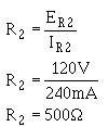
Using this value for IR1, calculate the resistance needed for the next divider resistor. The current (IR2) is equal to the bleeder current plus the current used by load 1.
Given:

Solution:

The voltage across R2 (ER2) is equal to the difference between the voltage requirements of loads 2 and1, or 120 volts.
Calculate the value of R2.
Given:

Solution:

The value of the final divider resistor is calculated with IR3 (IR2 + I load 2) equal to 340 mA and E R3 (Es - E load 2) equal to 25.5V.
Given:

Solution:

A 75-ohm resistor may not be easily obtainable, so a network of resistors equal to 75 ohms can be used in place of R3.
Any combination of resistor values adding up to 75 ohms could be placed in series to develop the required network. For example, if you had two 37.5-ohm resistors, you could connect them in series to get a network of 75 ohms. One 50-ohm and one 25-ohm resistor or seven 10-ohm and one 5-ohm resistor could also be used.
A parallel network could be constructed from two 150-ohm resistors or three 225-ohm resistors. Either of these parallel networks would also be a network of 75 ohms.
The network used in this example will be a series-parallel network using three 50-ohm resistors.
With the information given, you should be able to draw this voltage divider network.
Once the values for the various divider resistors have been selected, you can compute the power used by each resistor using the methods previously explained. When the power used by each resistor is known, the wattage rating required of each resistor determines the physical size and type needed for the circuit. This circuit is shown in figure 3-67.
Figure 3-67. - Practical example of a voltage divider.

In figure 3-67, why is the value of R1 calculated first?
In figure 3-67, how is (a)
the current through R2 and (b) the voltage drop across R2 computed?
In figure 3-67, what is the power dissipated in R1?
In figure 3-67, what is the purpose of the series-parallel network R3, R 4, and R5?
In figure 3-67, what should
be the minimum wattage ratings of R3and R5 ?
If the load requirement consists of both positive and negative voltages, what technique is used in the voltage divider to supply the loads from a single voltage source?
|
|


