Custom Search
|
|
 
|
||
|
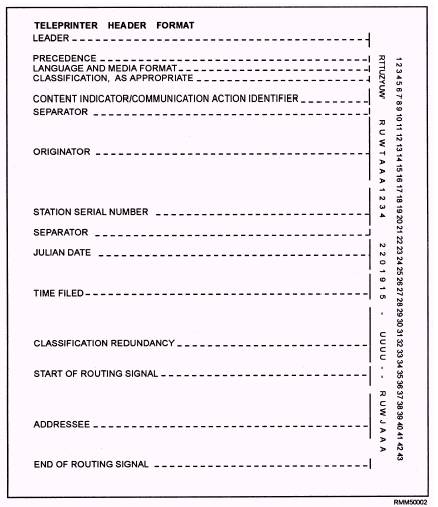
ROUTING INDICATORS. -Within the AUTODIN network, a message tape is routed through the AUTODIN system to the addressee(s) by a routing indicator. Routing indicators are combinations of not less than four nor more than seven letters. A routing indicator begins with the letter R or Q. The letter R indicates that the routing indicator is part of the worldwide tape relay system. The letter Q indicates that the routing indicator is within a self-contained network within a command or theater. The second letter of the routing indicator identifies the nation or international alliance to which the indicator belongs. For example, the letter U refers to the United States. Therefore, RU indicates that the message tape is part of the worldwide network and is destined to a station in the United States. The third letter of the routing indicator identifies the geographical area in which a particular station is located or from which it is served. This is necessary for relay purposes because the second letter may indicate a large nation within which there are a number of subdivisions or stations. For example, many stations in the United States are designated by the third letter C. Therefore, the first three letters of "RUC" indicate that the tape is part of the worldwide network, destined for the United States, and to a certain geographical area within the United States. The fourth and subsequent letters of a routing indicator designate relay and tributary stations within the tape relay network. Like the first three letters, the fourth and subsequent letters may vary, depending upon location, area, and other factors. TRANSMISSION IDENTIFICATION (FORMAT LINE 1). -As a means of maintaining traffic continuity, TTY terminals (modes II, IV, and V) must prefix each message header with a message transmission identification (TI). The ASC validates the elements in the TI. Modes I and III do not require format line 1. The TI is constructed without spaces and must be accurately prepared without corrections. For example, a correctly prepared TI might appear as follows: VZCZCJTA (FIGS) 123 (LTRS) (2CR 1LF) The elements of the TI and their meanings are as follows: l V -Ensures that the first character of intelligence is not lost or garbled; l ZCZ -Indicates the start of the message; . JTA -Station/channel designator letters; . xxx -Three-digit number indicating the sequential number of transmissions. The station/channel designators vary for each channel and are determined by the status of the originating station. For example, if a minor relay or tributary station originates a TI to a major relay station, the first two characters consist of the fifth and sixth letters of the station routing indicator. The third character identifies the channel. Channel designators start with the letter A, progress alphabetically, and are assigned to all connected channels. For example, a tributary station having the routing indicator RUWTABA would use the designator "ABA" for the first outgoing channel and "ABB," "ABC," and so on, for additional outgoing channels. MESSAGE HEADER (FORMAT LINE 2). -The message header is a basic 43-position header (figure 1-2). The message header is the starting point for the operator who is preparing the message tape. When preparing the header, the operator must remember that it must be letter-perfect. The following paragraphs describe each position of the header: Position 1 (Precedence) -The prosign Z (FLASH), O (IMMEDIATE), P (PRIORITY), or R
Figure 1-2.-Message header (format line 2). (ROUTINE) is the first element. The prosign Y (YANKEE) is an emergency command precedence (ECP) and is assigned to emergency action messages (EAMs). The prosign Y indicates that a message has FLASH preemption capability. EAMs are processed ahead of all other traffic and interrupt lower precedence traffic already in processing within the AUTODIN system. Positions 2 and 3 (Language and Media Format) -The language and media format (LMF) consists of two alphabetical characters. The LMF is the mode used to insert a message into the AUTODIN system. The LMF of the originating station is placed in position 2, and the LMF of the preferred output device of the addressee is placed in position 3. For example, in figure 1-2, positions 2 and 3 have the character T. The character Tin position 2 indicates that the originator's transmitting mode is paper tape (TTY/teleprinter) (five-level ITA2 code). The character T in position 3 indicates that the output device at the receiving end will be paper tape (TTY) (five-level ITA2 code). If the character C was used in position 3, this would indicate that the message was prepared and transmitted on paper tape and the output device at the receiving message center would be magnetic tape. Automated Digital Network (AUTODIN) Operating Procedures, JANAP 128, lists the LMFs used in the AUTODIN system. Position 4 (Classification) -The letters authorized to indicate the message classification or special handling in this position are:
Positions 5 through 8 (Content Indicator Code [CIC]/Communication Action Identifier [CAI]) -These positions of the header are a combination of either four letters or three letters and one number. These combinations are used to indicate message content and to provide identification for communications handling. For example, in figure 1-2, the CAI in positions 5 through 8 is ZYUW. This identifies the message as a narrative message. A CAI of ZFH2 would mean that the message is being forwarded to the addressee for information only. A CAI of ZYVW would indicate that the message is a service message. A complete listing of these codes is found in JANAP 128. Position 9 (Separator) -At this point in the header, the operator must press the space bar to insert the TTYcode equivalent for space on the message tape. Positions 10 through 16 (Originator) -The appropriate routing indicator of the originating station is placed in these positions. Positions 17 through 20 (Station Serial Number) -The station serial number (SSN) of the sending station is inserted here. The SSN serves two specific purposes. First, when used in combination with the originator's routing indicator, it provides positive identification for each transmission. Second, in the end of message (EOM) validation (discussed later in this section), the SSN appearing in format line 15 provides a means by which the ASCs can check for the existence of straggler messages. The SSN is expressed in four numeric characters, beginning with 0001 and continuing consecutively through 9999. A new series begins when the number 9999 is reached. Operating stations may use SSNs to identify local activities, channels, or positions within a station by assigning each activity a specific block of numbers. For example, one station may be assigned numbers 0001 to 2000; the next station 2001 to 4000, and so on. Position 21 (Separator) -This position requires the same information as that for position 9. Positions 22 through 24 (Julian Date) -The Julian date is the date that the message was received from the originator for transmission by the communications center. The first day of the calendar year is Julian 001, and each day is numbered consecutively thereafter. Positions 25 through 28 (Time Filed) -The time filed is the time that the message was received from the originator by the communications center for transmission. Each filing time is expressed in Greenwich mean time (GMT) and must contain four numerical characters. Positions 29 through 33 (Classification Redundancy) -For security reasons, the classification designator used in position 4 is repeated here. Position 29 is filled with a hyphen as a sentinel. The classification designator in position 4 is repeated in positions 30 through 33. of-routing signal and addressees) -The positions reserved for routing are made up of two sections: start-of-routing signal and the addressees' routing indicators. The start-of-routing signal consists of two consecutive hyphens and will always precede the first addressee routing indicator. Addressee routing indicators are listed immediately following the start-of-routing signal. A message can have a maximum of 500 routing indicators in these positions. If a message contains 501 or more routing indicators, the message will require two separate transmission. In this case, all routing indicators that have the same first four letters should be in one transmission End-of-Routing Signal -The end-of-routing signal consists of a period (.) and is inserted in the position immediately following the last addressee routing indicator. |
 
|
|
|
||