Custom Search
|
|
 
|
||
|
CHEMICAL LIGHT WAND The chemical light wand (fig. 3-58) is used to illuminate the projectile during night operations. The light wand is installed by inserting it, tapered end first, into the hole and groove of the projectile. The light wand is a two-component chemical illuminate system consisting of a yellow-green oxalate solution inside a nylon tube. To activate the light, flex the nylon tube enough to break an inner glass tube, as shown in figure 3-59, and shake well. Do not activate
Figure 3-58.-Chemical light wand.
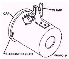
Figure 3-59.-Activating chemical light wand. the light wand until ready to use because once it is activated it must be used or disposed of. Do not dispose of the chemical light wand overboard as it may be mistaken for a "man overboard exercise. WARNING If the nylon tube should puncture during activation, individuals may experience some mild discomfort from excessive skin or eye exposure to the oxalate solution. Personnel should wash exposed areas with soap and water as soon as possible. Since the chemical light produces no flame or heat, its stowage is not restricted to ventilated and unconfined (topside) spaces. The active life of the chemical light is from 3 to 12 hours, depending on the ambient temperature. Its shelf life is approximately 2 years under normal conditions. CANISTER The canister (fig. 3-60) is made of polyethylene and houses the spool of shot line when attached to the appropriate rifle. Attachment is made by the metal clamp shown in figure 3-60.
Figure 3-60.-Canister. To install the shot line in the canister, remove the cap from the after end of the canister. Place the spool of shot line in the canister and feed the line from the center of the spool through the hole in front of the canister. Tie knot in the bitter end of the shot line and slide it into the slot at the after end of the canister. Replace the canister cap. (The action of placing the knotted end of the shot line into the canister slot attaches the bitter end of the shot line to the canister.) Connect the line coming from the front end of the canister to the loop line on the projectile. These lines (shot line and loop line) are connected by a series of loosely tied half-hitch knots (three to five). Figure 3-61 shows the canister, shot line, and launcher mounted on the M14 rifle. Note in figure 3-61 that the use of the canister is optional. With another person holding the shot line, the canister is not needed. The canister is part of the Mod 0 kit and should be retained for optional use with the Mod 1 kit. RECOIL PAD The recoil pad provided by this kit will reduce the recoil on the operator when the projectile is launched. It is of the slip-on type and made of neoprene rubber that resists attacks by oil and other solvents. It is designed for a tight fit on the butt stock Thus care is required during installation to prevent tearing. Once installed on the rifle used for line throwing, it is recommended that the recoil pad not be removed. The pad is designed to fit both the M14 and M16A1 rifles. However, on the M16A1 rifle, the sling swivel is closer to the rifle butt and the skirt of the recoil pad must be folded back or cut to fit around the swivel. The recoil pad is shown installed on the M14 rifle in figure 3-61. |
 
|
|
|
||