Custom Search
|
|
 
|
||
|
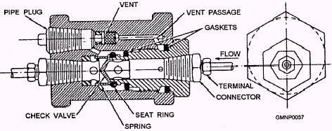
Transmission Lines The transmission lines that connect the thermopneumatic elements to the PRP are rockbestos or rockhide-covered seamless copper tubing. Vented Check Valve The vented check valve (fig. 2-22) is a brass, spring-loaded check valve that is designed to check against a rapid change of air pressure in one direction and to open when air pressure is applied in the other
Figure 2-22.-Vented check valve. direction. One vented check valve is installed in each transmission line (above the PRP and maximum of 12 per PRP) from an HSD with the direction-of-flow arrow pointing toward the PRP. Since the PRP manifold contains only six ports for transmission tubing connection, systems requiring seven or more HSDs will "Tee" together vented check valves, starting with the seventh check valve. The check valves prevent the rapid increase in air pressure created in an individual HSD from pressurizing the entire system. The check valve body contains a vent installed in a bypass around the main valve. The vent permits a slow backflow of air to equalize system pressure in response to normal changes in ambient temperature. Pneumatically Released Pilot (PRP) Valve The PRP valve (fig. 2-23) is a normally closed spring-loaded pilot valve that opens automatically to actuate the magazine sprinkler system in response to a pneumatic signal from one or more thermopneumatic elements. The main components of the PRP valve are the operating mechanism, the compensating vent, and the pilot valve. The operating mechanism and compensating vent are housed in a circular bronze case. The pilot valve is mounted on the front of the case. The pilot valve is installed in a 3/8-inch line that connects the firemain to the sprinkler system hydraulic control system piping. The PRP valve case is provided with shock mounts and brackets for fastening to a bulkhead. The operating mechanism consists of a spring-loaded operating lever operated by a release diaphragm through a series of linkages and levers. The rear of the release diaphragm is connected to the tubing from the HSDs. The front of the release diaphragm is open to the interior of the PRP valve case. The compensating vent connects the two sides of the diaphragm. The diaphragm moves to trip the release lever in response to either a sudden or gradual increase in pressure transmitted from one or more HSDs. When the PRP valve is set, the operating lever is cocked to hold the valve closed. When the PRP valve is tripped, the operating lever is released to rotate through a clockwise
Figure 2-23.-Pneumatically released pilot (PRP) valve. arc. The angular motion is transmitted to the pilot valve lever by a connecting shaft. The pilot valve is a cast bronze assembly that houses the valve seat and the seat holder. The end of the pilot valve outlet piping serves as the seat. The seat holder is a Monel cylinder that contains a rubber seat disk bonded to one end and an adjusting screw and locknut on the other end At assembly, the ball end of the pilot valve lever is inserted in the middle of the seat holder between the adjusting screw and the shoulder of the seat disk. An antichatter spring is provided between the ball of the lever and the back of the seat disk. The pilot valve lever is designed to pivot about a pin fastened to the PRP valve case. When the PRP valve release diaphragm is tripped, the movement of the pilot valve lever causes the seat holder to move away from the seat, thereby permitting seawater to enter the hydraulic control system piping and actuate the sprinkler system. The PRP valve is equipped with a compensating vent that functions to "leak off" the slight increases or decreases of pressure within the HSDs caused by normal temperature fluctuations in the protected compartment. This leakoff of slow pressure changes equalizes the pressure on both sides of the release diaphragm and prevents inadvertent tripping of the PRP valve. The compensating vent is calibrated and adjusted at the factory. No adjustments should be undertaken by ship's force. Accordingly, the rate-of-rise circuit is designed to trip the PRP valve and actuate the sprinkler system when sufficient heat is absorbed by the HSDs to create a definite pressure within the circuit over a given period of time. This pressure acts against the rear of the release diaphragm to create the pressure differential necessary to trip the PRP valve. A slower rate of heat absorption will not cause the system to function, as provision is made within the PRP valve to compensate for normal temperature changes in the protected space. |
 
|
|
|
||