Custom Search
|
|
 
|
||
|
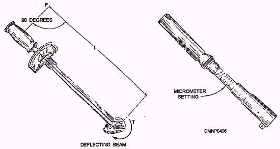
MAINTENANCE TOOLS LEARNING OBJECTIVES: Describe the use of common hand tools, power tools, types of torque wrenches, and special tools used in gun mount maintenance. You must be familiar with the techniques and tools required to maintain, repair, and adjust ordnance equipment. Further, a GM must be able to select the proper general-purpose tools and special tools and know the safety rules applicable to their use. Maintenance tools can be classified as follows: . General-purpose hand tools l Power tools . Measuring tools and gauges . Torque tools . Special tools HAND TOOLS General-purpose hand tools are hand-powered and hand-operated. They are designed to perform simple mechanical operations. Examples of typical hand tools are hammers, screwdrivers, and hacksaws. General information about hand tools is in Use and Care of Hand Tools and Measuring Tools, NAVEDTRA 12085. POWER TOOLS Power tools can either be electrically or pneumatically powered and are hand-operated. They are designed to save time and manpower, Examples of power tools used by the Gunner's Mate are soldering guns, electric drills, and pneumatic grinders. MEASURING TOOLS AND GAUGES Measuring tools and gauges are used for measuring and for layout work. Accurate measurements are essential for proper fitting and trouble-free equipment operation. Measuring tools and gauges range from a simple ruler to a highly accurate micrometer. Use and Care of Hand Tools and Measuring Tools gives a detailed discussion on all types of measuring tools and gauges that includes the common steel rules, calipers, micrometers, dial indicators, feeler gauges, and depth gauges. When studying Use and Care of Hand Tools and Measuring Tools, pay particular attention to reading micrometers and how to make feeler gauge readings. These two measuring tools are used for testing, checking, and adjusting many types of electrical, mechanical, and hydraulic units used with ordnance equipment. TORQUE WRENCHES There are times when, for engineering reasons, a definite pressure must be applied to threaded fasteners (nuts and bolts, as they are commonly called). This pressure can be properly applied by a torque wrench. Proper torque aids in the locking of all types of thread-locking fasteners. After tightening, nuts and bolts are held by the static friction of the nut and bolt head against the surface of the items being held together and the friction on the threads of the nut and bolt against each other. This friction is caused by the clamping force created by a slight stretching of the bolt when the nut is tightened. The metal, being slightly elastic, will pull back toward its original dimensions, creating large clamping forces. Excessive tightening will cause the metal to pass its limit of elasticity and cause a permanent stretch. The principle of torque is based on the fundamental law of the lever; that is, force times distance equals a moment, or torque, about a point. Torque is often called a torsional or twisting moment. It is a moment that tends to twist a body about an axis of rotation. For example, if a common-end wrench is used to tighten a bolt, a force times a distance, a torque is applied to overcome the resistance of the bolt to turning. Figure 12-7 shows three torque wrenches-the deflecting beam, the dial-indicating, and the micrometer-setting types. The deflecting beam is probably the simplest and most common. The primary component is the beam or measuring element. It is made of alloy steel and maybe round, double round, straight flat, or tapered flat. To one end of the beam is attached a headpiece containing the drive square (tang) and fixed pointer mounting. A yoke is attached to the other end. Mounted on the yoke is the torque scale handle and, when provided, the signaling mechanism. As a force is applied to the handle, the beam deflects with the scale. The pointer remains fixed; hence, a torque is indicated on the scale. The torsion bar or rigid case dial-indicating type of wrench, also shown in figure 12-7, has its actuating element enclosed in a rigid frame with a removable access cover. The deflecting beam, used in some rigid case wrenches, is similar to that explained previously.
Figure 12-7.-Torque wrenches. 12-24 The third torque wrench shown is the micrometer-setting type. To use this wrench, unlock the grip and adjust the handle to the desired setting on the micrometer type of scale, then relock the grip. Install the required socket or adapter to the square drive of the handle. Place the wrench assembly on the nut or bolt and pull in a clockwise direction with a smooth, steady motion. There are several different types of torque wrenches, but all of them have two basic parts-something that will deflect with the load and something to show how much the sensing element has deflected. The torque wrench should be calibrated frequently. One that has not been recently calibrated and is not normally stowed in its protective case should be considered as a dangerous tool. You cannot expect to get a meaningful reading from a precision instrument that has been abused. The flat- and round-deflecting beam types will normally give true readings as long as their pointers indicate zero and the drive heads are tight. Because this type can be kept in calibrations, it is recommended for shipboard use. Other types of wrenches that indicate by means of dial indicator or by releasing or signaling when a preset load is reached are more sensitive to shock and dirt, hence should be calibrated whenever possible. A minimum of 30 days between calibrations is recommended. Never check one torque wrench against another. An important point to remember always use the proper size wrench-the one with the desired torque near the three-fourths mark of full scale. When torquing, the critical maneuver is the application of force to the wrench handle. It must be applied slowly and evenl y until the desired torque value is indicated on the wrench scale. When installing a unit that is circular or has more than one side, you should cross-torque the bolts. It may be necessary to cross-torque two to three times before an even torque is reached, but be sure the maximum torque is not exceeded. Nuts and bolts should be tightened to the torque reading required by the installation drawings. The formula often used is torque in foot-pounds is 0.2 times the bolt diameter times the desired bolt load. A load of about 60 percent of the yield stress of the bolt material is used for most naval applications. However, bolt load varies depending upon whether the bolt or stud is used to support the load itself or to hold together two load-supporting members. Installation drawings will indicate the torque value specified by the designer. If the bolts are loaded in tension, the torque must be great enough to maintain tightness when the assembly is unloaded and not so large that the bolts yield under load With this type of loading, all bolts must be equally torqued to share the load. NOTE: Always inspect for clean, lightly oiled threads and clean surfaces before torquing. Discard all hardware with burred threads. For more detailed information on the use and care of torque wrenches, refer to Naval Ships' Technical Manual (NSTM), chapter 075. SPECIAL TOOLS Special tools are used for one purpose and only on one type of equipment. They are supplied by NAVSEA, and instructions for their proper use are provided in the Ops applicable to the specific type of equipment. |
 
|
|
|
||