Custom Search
|
|
 
|
||
|
STANDARD GMTR The current version of the GMTR is designated the Mk60 Mod 6, 7. It is capable of simulating ITR, SM-1A (MR), SM-1 (MR), SM-2 (MR), Standard ARM, and Harpoon missiles. Externally, the GMTR is similar to a tactical SSSM round. Although the sections and markings are not the same, the GMTR adequately serves for all general handling and display purposes. The Mk 60 Mod 6, 7 GMTR is made up of two major subassemblies: 1. Mk 59 Mod 3 guided missile dummy round (GMDR) 2. Mk 63 Mod 5, 6 guided missile simulator (GMS) The GMDR (fig. 10-19) forms the body of the GMTR. It consists of ballasted dummy sections and is painted blue. Tail control surfaces and dorsal fins are painted white. The Mk 63 Mod 5, 6 GMS is located in a compartment of the dummy rocket motor section. A removable door protects the simulator from the outside elements. The door has a clear plastic window to permit visual observation of switch positions and lamp displays. A target acquisition console (TAC) source and emitter are mounted in the adapter section of the GMDR. These units are used in testing Standard ARM missile features. The dummy rocket motor igniter assembly is mounted in the forward part of the dummy
Figure 10-19.-Mk 60 Mod 6, 7 GMTR for Standard missile systems.
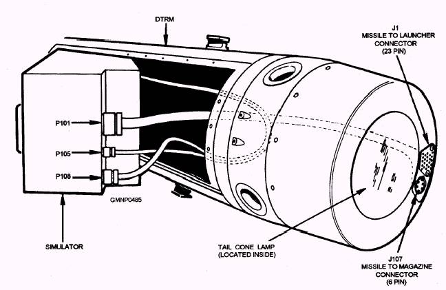
Figure 10-20.-GMTR dummy igniter and S&A lever. DTRM (fig. 10-20). Four firing contact buttons and the S&A (SAFE/ARM) levers are also located here. The tail cone assembly of the GMDR includes two external electrical connectors (fig. 10-21). The six-pin missile-to-magazine connector provides for round identification and application of warmup power (if applicable). The missile-to-launcher connector (MLC) provides a 23-pin jack receptacle for application of preflight missile orders and simulator power. The MLC is easily removed/replaced and protected by a rubber composition pad. The tail cone assembly houses a large red light bulb called the tail cone lamp. When a firing circuit is completed, the lamp lights to simulate rocket motor ignition. The aft end of the tail cone is sealed with a clear plastic window. The tail cone lamp is easily observed through this window. Figure 10-21 also illustrates how a GMS is installed and connected (electrical cables) to the GMDR. The Mk 63 Mod 5, 6 GMS is a very versatile electronic unit. Figure 10-22 shows the front panel of the simulator. The GMS furnishes the electrical loads, voltages, frequencies, and responses for any of the six missile types mentioned earlier. Around identification switch (item 1 in the figure) selects the correct circuits
Figure 10-21.-Tail cone assembly components and simulator removal. 10-24
Figure 10-22.-Mk 63 Mod 5, 6 front panel of the guided missile simulator. for simulation of the desired missile type. Lamps, switches, displays, and test jacks on the front panel facilitate DSOT and other system testing. Most of the major simulator circuits are designed to function independently. They also have associated indicators to display readouts of their operations. The roll corrector circuit includes an LED display (item 21 in the figure) for direct reading in degrees of roll. Visual readout of the selected missile cede or channel number (item 22 in the figure) is also displayed on an LED readout. |
 
|
|
|
||