Custom Search
|
|
 
|
||
|
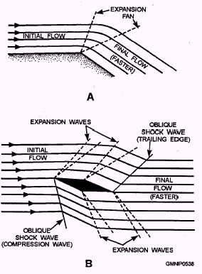
Rate Gyros in Guided Missiles The free gyros just described measure and generate correction signals necessary to maintain a stable attitude. However, because of the momentum of the missile in responding to these signals, another problem develops. Large overcorrection would result unless there were some way of determining how fast the angular movement is occurring. In other words, the missile would overshoot and oscillate around the given axis. Rate gyros (shown in view B of fig. 9-8) take into account the momentum of the missile and continuously determine any angular accelerations. By combining the free and rate gyro signals, the tendency of the control surfaces to overcorrect is minimized and better in-flight stability is obtained. Normally, there is an independent rate gyro for each (roll, pitch, and yaw) axis. CONTROL SURFACES Aerodynamic control is the connecting link between the guidance system and the flight path of the missile. Effective control of the flight path requires smooth and exact operation of the control surfaces of the missile. They must have the best possible design configuration for the intended speed of the missile. The control surfaces must move with enough force to produce the necessary change of direction. The adjustments they make must maintain the balance and center of gravity of the missile. The control surfaces must also be positioned to meet variations in lift and drag at different flight speeds. All these actions contribute to the in-flight stability of the missile. Stability and Lift So far we have discussed the principles of producing lift by using chambered or curved airfoils. Chambered airfoils are mainly used on subsonic, conventional aircraft. The present-day supersonic guided missile must use a different kind of control surface to provide stability and lift. In most SMS missiles, lift is achieved almost entirely by the thrust of the propulsion system of the missile. The control surfaces must, therefore, be streamlined to reduce any resulting air turbulence. The lift that a missile fin does contribute is based on a slightly different principle than that seen in figure 9-6. At subsonic speeds, a positive angle of attack on the fins of the missile will produce lift just as with the conventional airfoil. However, at supersonic speeds, the formation of expansion waves and oblique (angled) shock waves also contribute to lift. View A of figure 9-11 shows the upper surface of a supersonic fin in detail. Because of the shape of the fin, the air is speeded up through a series of expansion waves, resulting in a low-pressure area above the fin. View B of figure 9-11 shows a full cross section of the fin. Beneath it, the force of the airstream and the formation of oblique shock waves results in a high-pressure area. These pressure differences produce lift. Fin Designs and Arrangements Figure 9-12 shows the basic design shapes of supersonic fins. In view A, the double wedge offers the least drag but lacks strength. The modified double wedge has relatively low drag and is stronger. The biconvex causes considerable drag but is the strongest of the three designs. The biconvex is also the most difficult and expensive to manufacture. View B of figure 9-12 shows the side view of popular supersonic fin designs. These particular shapes are used to reduce unwanted shock wave effects. Fins can be mounted on the structure of the missile in many different arrangements. Figure 9-13 shows some of the variations. The cruciform style is the most predominant in SMS missiles.
Figure 9-11.-View A.-expansion wave; View B.-airflow around a supersonic fin.
Figure 9-12.-High-speed fin configurations. |
 
|
|
|
||