Custom Search
|
|
 
|
||
|
SUPPLY CYLINDERS.- GMLS fixed CO2 systems usually have at least two supply cylinders. Each cylinder has a 50-pound CO2 capacity and weighs 165 pounds when fully charged. It contains liquid carbon dioxide under a pressure of 850 psi at 70F. Each cylinder of the system has a discharge head and a cylinder valve. At least one of the cylinders will also have a pneumatic control head. The other
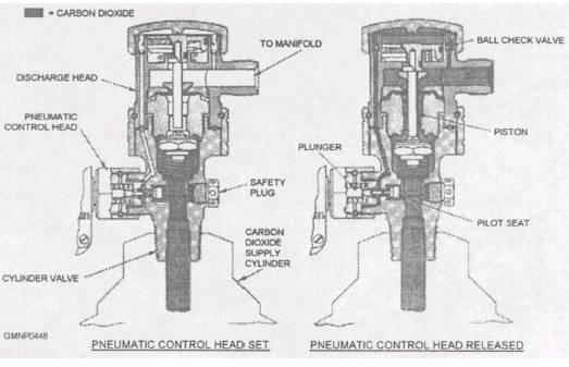
cylinder(s) will be in tandem with the main control cylinder(s). See figure 821. Pneumatic Control Head.- A pneumatic control head (shown in fig. 8-21) reacts to HSD pressure signals or to manual operating levers. The control head is tripped to open the discharge head and cylinder valve, which release the liquid CO2 from the cylinder. The control head consists of an air chamber with a diaphragm. The control head also has two plungers, safety locking pins, and a manual (local) operating lever. The pressure chamber in the control head has an orifice that vents air pressure at a predetermined rate. When pressure in this chamber increases faster than it can be vented, the diaphragm expands. This movement trips a lever that releases a trigger mechanism. The trigger mechanism shifts the two plungers. Shifting the plungers opens the pilot seat in the cylinder valve. Cylinder Valve and Discharge Head.- The cylinder valve and discharge head are shown in figure 822. Together, they block the escape of the liquid CO2 from the cylinder until the control head is activated. When the plungers from the "tripped" control head open the pilot seat, CO2 flows into the chamber above the discharge head piston. The piston is shifted (down) against its spring. The ball check valves trap gas pressure in the upper chamber. This keeps the piston open (down) and ensures rapid and complete cylinder discharge. Shifting the piston opens the cylinder valve, allowing CO2 to flow to the exhaust manifold and supply lines. (See fig. 8-21.) DISCHARGE NOZZLES.- CO2 discharge nozzles are installed so that their discharge blankets certain key electrical components. The nozzles are also located so that the entire area they serve is flooded with CO2. The nozzle is a bell-shaped device (fig. 8-20)
Figure 8-22.-Cylinder valve and discharge head schematic. 8-25 with an orifice at its discharge point. The orifice restricts the discharge of the CO2 and creates an even flow from all system nozzles. The gaseous "snow" of CO2 quickly extinguishes the fire. MISCELLANEOUS COMPONENTS.- A manually operated shutoff valve is installed in the CO2 discharge line between the supply cylinders and discharge nozzles. (See fig. 8-21.) The valve is physically located outside the magazine near its entrance. To avoid a CO2 suffocation hazard, unlock the valve and close it before you enter the magazine. If the system should activate, the supply cylinders will release CO2. However, the closed valve will stop the CO2 so that you can keep breathing. CO2 pressure entering the supply line activates an operation alarm switch (fig. 8-21). Audible alarms and lights are turned on, signaling that the CO2 system has activated. These warning devices are usually located right outside the magazine area and at the ship's damage control (DC) central room. The switch must be manually reset if activated. The alarm circuits maybe maintenance-tested. A remote control pull box allows personnel to release the pneumatic control head(s) manually. The pull box is located outside the magazine. It has a transparent, breakable shield and a pull handle. A wire cable is connected to the control head trigger mechanism. Breaking the glass and pulling the handle activates the system. The CO2 system can also be activated locally. Manually removing a safety pin and tripping a lever on the pneumatic control head releases the CO2. Actual GMLS CO2 Systems Every GMLS has some type of CO2 fire-fighting capability. Some GMLSs have a combination of fixed
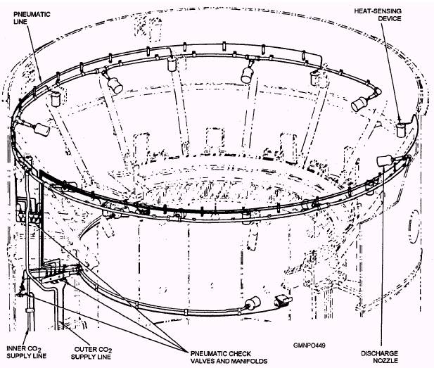
Figure 8-23.-Arrangement of inner and outer CO2 systems. and portable CO2 protection. Other GMLSs only have portable extinguishers available. System design and configuration sometimes restrict the installation of fixed CO2 system hardware. The Mk 26 GMLSs do not have a fixed CO2 system. Portable extinguishers, readily accessible throughout key areas of the GMLSs, provide the protection. The Mk 13 GMLSs do have fixed CO2 systems in addition to portable extinguishers. The Mk 13 GMLSs have separate inner and outer magazine CO2 systems (fig. 8-23). The inner system covers the center column or inner structure. The outer system floods the RSR area. |
 
|
|
|
||