Custom Search
|
|
 
|
||
|
STRIKEDOWN LEARNING OBJECTIVES: Identify the major components of the major GMLS systems, and describe the operational procedures for strikedown of these systems. Strikedown is a term associated with special GMLS equipments, operational procedures, and modes of system control. They are used during a missile onload or missile offload process. An ondoad operation transfers missiles from an outside source into the missile magazine. An offload operation is just the opposite. Strikedown, for our purposes, is strictly an in-house GMLS operation. How a missile is transferred between a supplying activity and a receiving activity comes under the topic of replenishment. As GMs, we are generally not responsible for the actual replenishment actions. However, we must be aware of the basic procedures. Our main task is to move the missile between the ship's replenishment area and the GMLS strikedown area safely. Guided-missile replenishment can be performed in various ways. Underway replenishment (UNREP) can be in the form of a connected replenishment (CONREP) or a vertical replenishment (VERTREP). For CONREP, missiles are moved between ships on appropriate riggings or highlines. For VERTREP, a helicopter is used to deliver/remove missiles from the ship. VERTREP may also be performed while the ship is at anchorage and, in some rare cases, pierside. A crane is used during dockside or lighter replenishment. (A lighter is an ammunition barge.) The crane is the simplest of replenishment methods. We will examine replenishment methods in greater detail later. For now,
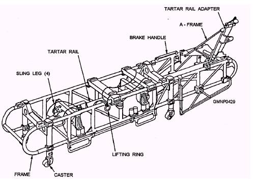
Figure 8-3.-Transfer dolly. we will stay with the strikedown operations performed by the GMLSs. MK 13 MOD 4 GMLS STRIKEDOWN The strikedown onload and offload operations of the Mk 13 Mod 4 GMLS require special strikedown handling equipment, which must be installed on the launcher. This equipment provides a pneumatically driven chain mechanism to transfer the missile between the guide arm and transfer dolly (fig. 8-3). Figure 8-4 shows a Mk 13 Mod 4 strikedown operation with strikedown handling equipment installed.
Figure 8-4.-Mk 13 Mod 4 GMLS strikedown operations.
Figure 8-5.-Typica1 strikedown hand-control unit. Transfer dolly handling and most launcher and guide arm component movements are initiated and controlled by system personnel topside. Strikedown Gear The special Mk 13 Mod 4 GMLS strikedown gear consists of a hand-control unit, a chain-drive fixture, and air supply components. This gear is stowed near the launcher area and must be set up before onload operations begin. Strikedown air originates from the ship's HP air system. At the GMLS, HP air is reduced and regulated to the low-pressure requirements (about 100 psi) of the equipment. This arrangement provides the strikedown gear with sufficient operating volume and pressure. In the following discussion, we will call this reduced HP air "supply air." STRIKEDOWN HAND CONTROL.- The strikedown hand-control unit is a hand-held portable switch box. It is sometimes referred to as the deck control box. The operator of this unit can control train and elevation launcher movements, the elevation positioner (latch), and both power-drive brakes. The box has six toggle switches (five are functional) and six indicating lamps. A detachable cable connects the box to the strikedown jack receptacle of the GMLS. The receptacle is mounted on the stand or on a bulkhead outside the launcher control room. (Location varies between mark and mod of GMLS.) Figure 8-5 shows a typical hand-control unit. Note what functions are controlled and indicated by the switches and lamps. CHAIN-DRIVE FIXTURE.- The chain-drive (or strikedown) fixture is shown in figure 8-6. It is installed and locked to the front of the guide by two
Figure 8-6 - Chain Drive Fixture quick-release pins. Probes on the fixture actuate a strikedown-fixture-on-launcher interlock switch and deflect the retractable rail trigger. That prevents any interference between the trigger and the strikedown chain. The link-type chain is guided by the forward shoe tracks of the retractable rail. A pair of spring-loaded latches on the forward end of the chain engage the forward missile shoe. An air motor on the fixture drives the chain through a simple gear reduction and sprocket mechanism. As the chain is made to extend or retract, it pulls the missile up to the guide arm or lowers it to the dolly. Air motor operation is controlled by a pressure-regulating valve and an air-throttle valve. Both components are mounted on the chain-drive fixture. The pressure regulator reduces supply air to about 20-25 psi for a chain extend cycle. This low pressure drives the air motor at a slow extend speed. It also prevents the chain links from buckling when the latches engage the missile shoe. The air-throttle valve serves two purposes. First, it functions as a directional valve controlling the direction of motor rotation. Second, it controls the speed of chain travel near its extended and retracted limits. The valve throttles or reduces the air pressure available to the drive motor. MANUAL AIR-CONTROL VALVE.- The manual air-control valve is a three-position, hand-operated valve (see fig. 8-4). Air line hoses connect it to a convenient ship supply air source near the launcher. Other hoses connect it to the pneumatic components on the chain-drive fixture. The air-control valve is used to start, stop, and select the direction of chain travel. When the valve is in the NEUTRAL position, supply air is isolated from the drive fixture to stop the chain. When the valve is in the EXTEND or RETRACT position, supply air is ported to shift the air-throttle valve appropriately. |
 
|
|
|
||