Custom Search
|
|
 
|
||
|
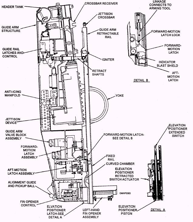
Aft-Motion Latch.- The aft-motion latch (fig. 7-5, Detail B) is located near the pivot point of the retractable rail. This device is a stop that prevents a missile from moving backward on the retractable rail. The latch is a hydraulic piston that extends behind the aft shoe of the missile. One of its associated mechanisms is a rod that mechanically detects when a missile is on the guide arm. This rod also provides a discharge path for electrostatic charges on the missile surface. Another plunger of the aft-motion latch pivots a piece on the hoist pawl to disengage it (hoist pawl) from the aft shoe of the missile. Forward-Motion Latch.- The forward-motion latch (fig. 7-5, Detail B) is a dual-purpose stop. It acts as a positive stop when the hoist raises a missile onto the retractable rail. Until missile firing or jettisoning, the latch also restrains the missile from moving forward on the rail and falling onto the deck. The latch is a steel piece that pivots into and out of the track chamber of the retractable rail, where it makes contact with the aft shoe of the missile. The forward-motion latch and its operating mechanism provide a 2,320-pound restraining force that holds the missile on the guide arm. When fired or jettisoned, the missile overcomes this force, pivoting the latch out of the track chamber. The forward-motion latch lock is a movable piece that bears against the forward-motion latch. The lock provides the positive stop when the hoist raises a missile onto the retractable rail. During the missile firing sequence, a release piston disengages the latch link. Through linkage, this action causes the arming tool to arm the missile. The Mk 13 also has a key-operated lock in the release piston linkage. When closed, the key-operated lock prevents the forward-motion latch lock from disengaging and, in turn, causing the missile to arm. The launcher captain uses the keylock as a safety device to prevent accidental arming of the rocket motor during missile checkout or inspection.
Figure 7-5.-Guide arm. FIN OPENER AND CONTACTOR AS-SEMBLY.- Functionally, the identification probe (fig. 7-6) is used twice in system operation. During an initial strikedown on-load of a missile, the fin opener assembly is extended to the missile. The probe connects the missile-type information to the control system of the launcher. There it is stored in the identification memory circuits as missile-type and cell-location data. When this action is accomplished, the fin opener assembly is disengaged and the missile may be unloaded into a cell. During a load-and-fire operation, the fin opener assembly and probe are engaged again to recheck missile identification. If the type of missile on the guide matches the type of missile ordered from the RSR, preflight orders/Harpoon warmup are applied to the missile. Otherwise, circuits to the 23-pin contactor will remain open and the incorrect missile cannot be launched. ELEVATION POSITIONER.- The elevation positioner consists of a hydraulic piston and a latch at the aft end of the guide arm structure (fig. 7-5, Detail A). When the blast door is open and the launcher guide is at 90 elevation, the tapered nose of the piston extends down to engage a spud on the door. This locks the launcher guide to the carriage. The piston, or positioner, retracts up into a bore within the guide arm structure to allow launcher elevation movements. The latch prevents the positioner from springing out due to a loss of hydraulic fluid pressure or because of vibration. Carriage The carriage (fig. 7-7) is mounted on the magazine stand and is the support structure for the launcher guide. The carriage rotates in response to mechanical movements of the train power drive and transmits the mechanical movements of the elevation power drive to the launcher guide. In addition, the carriage connects
Figure 7-6.-Right-hand fin opener and contactor assembly.
Figure 7-7.-Launcher carriage. the launcher guide with electrical cables, hydraulic lines, and anti-icing lines. The main components of the carriage are a right-hand trunnion support, a left-hand trunnion support, and a base ring. |
 
|
|
|
||